Bracket surface milling, hole drilling and circular arc milling manual tool for machining center

A machining center and tooling technology, used in metal processing equipment, metal processing mechanical parts, supports, etc., can solve the problem of pin holes being prone to yielding knives, etc., and achieve the effect of improving stability

Inactive Publication Date: 2018-12-21
JIANGSU UNIV
View PDF14 Cites 3 Cited by
  • Summary
  • Abstract
  • Description
  • Claims
  • Application Information

AI Technical Summary

Problems solved by technology

[0004] Aiming at the deficiencies in the prior art, the present invention provides a manual tooling for milling, surface drilling, drilling and arc milling of a machining center, which mainly solves the problem of improving work efficiency, reducing labor intensity of workers, reducing the possibility of mixing materials in the development stage of processing samples and To avoid the problem that the inner part of the pin hole is easy to produce a knife phenomenon during deep hole machining due to insufficient rigidity of the main body of the tooling

Method used


Image

  • Bracket surface milling, hole drilling and circular arc milling manual tool for machining center
  • Bracket surface milling, hole drilling and circular arc milling manual tool for machining center
  • Bracket surface milling, hole drilling and circular arc milling manual tool for machining center

Examples


Embodiment Construction

[0027] The present invention will be further described below in conjunction with the accompanying drawings and specific embodiments, but the protection scope of the present invention is not limited thereto.

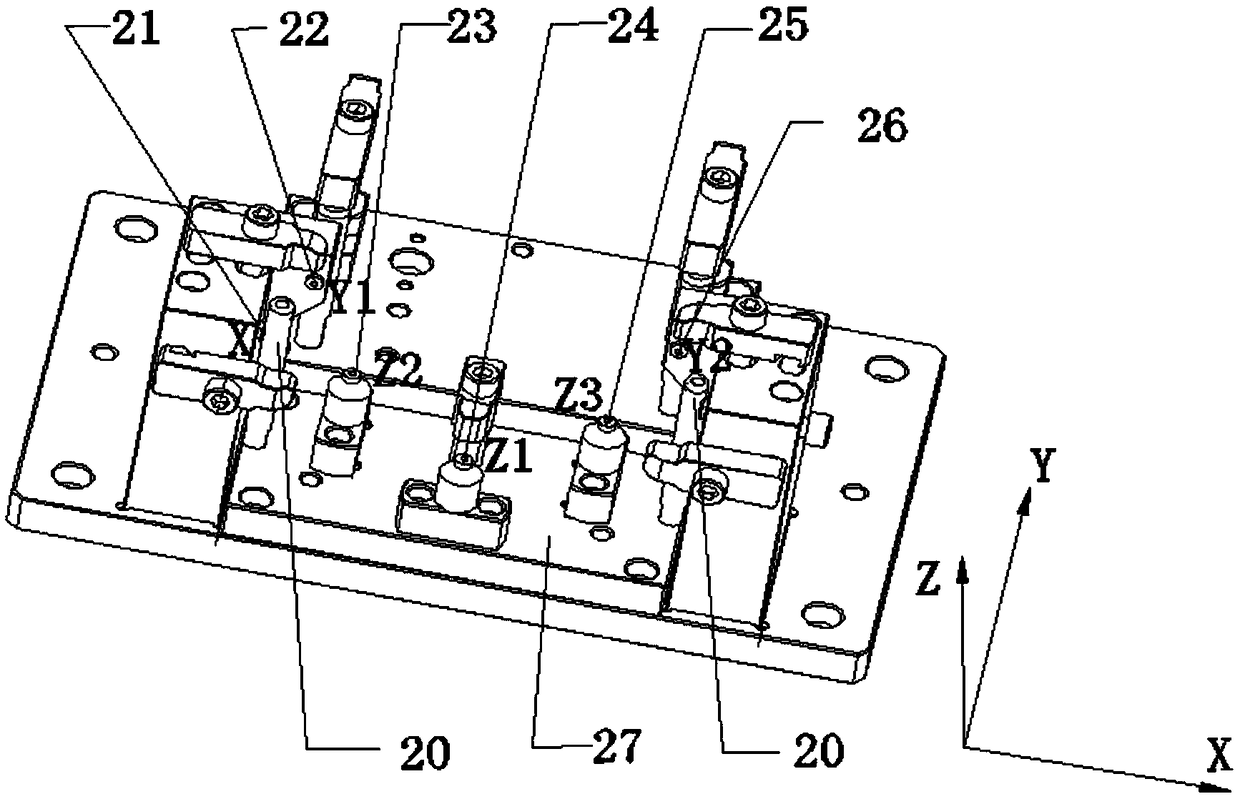
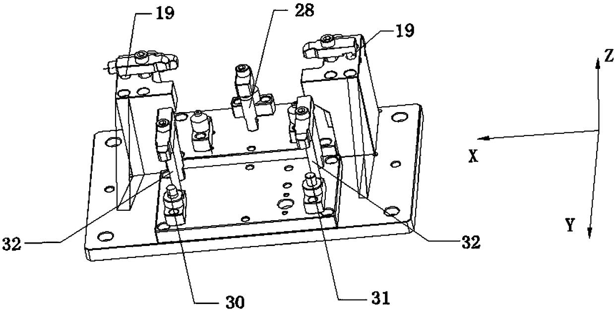
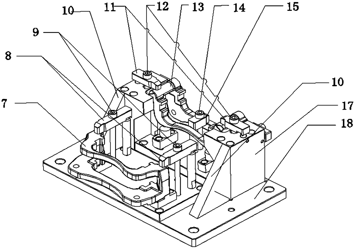
[0028] Such as figure 1 with figure 2 As shown, a manual tooling for milling, drilling, and arc milling with a bracket for a machining center includes a base plate, a first station clamp body for milling and drilling of a blank workpiece 13, and a second clamping body for milling and arc milling of a semi-finished workpiece 7. As for the clamping body of the station, the base plate includes a first base plate 18, a second base plate 27 and a third base plate 3, and the second base plate 27 and the third base plate 3 are installed on the first base plate 18, and the second base plate 27 and the third base plate 3 are installed on the first base plate 18. The three bottom plates 3 have the same size and are arranged side by side. The clamp body of the first station is ins...


PUM


Abstract

The invention provides a bracket surface milling, hole drilling and circular arc milling manual tool for a machining center. The bracket surface milling, hole drilling and circular arc milling manualtool for the machining center comprises a bottom plate, a first station fixture body and a second station fixture body, wherein the first station fixture body is used for milling surface of a blank workpiece and drilling a hole in the blank workpiece; the second station fixture body is used for milling a circular arc on a semi-finished workpiece; the first station fixture body and the second station fixture body are both mounted on the bottom plate; the second station fixture body comprises a first cylindrical pin, a third limiting pin, a prismatic pin and two second fixture units which are correspondingly used for clamping the two ends of a bracket; and the first station fixture body comprises a first positioning mechanism and two first fixture units, wherein the first positioning mechanism is used for positioning the blank workpiece, and the two first fixture units are used for clamping the two ends of the blank workpiece. According to the bracket surface milling, hole drilling and circular arc milling manual tool for the machining center, as the first sration fixture body used for milling the surface of the bracket and drilling the hole in the bracket and a second station fixture body used for milling the circular arc of the bracket are designed on the same platform surface, the machining rhythm is accelerated, the personnel cost in the sample development stage is saved, thelabor intensity of machine regulating personnel is reduced, and a material mixing phenomenon is avoided.

Description

technical field [0001] The invention relates to the field of brake bracket production, in particular to a bracket milling surface drilling drilling and arc milling fixture for a machining center. Background technique [0002] In the field of brake brackets, in order to reduce the risk in the project development process, before the official tooling is put into production, customers generally have manual tooling requirements for suppliers. On the one hand, the price of the formal tooling into production is considered, and the project Stability of the development process. Therefore, the design verification of manual tooling is particularly important. [0003] During the processing of the brake bracket, the general face milling, drilling and tapping are processed by the machining center, and the milling of the large arc is processed by the milling machine. Possibly, the occupancy rate of the machine and other factors, the two processes are merged into one tooling, and the main...

Claims


Application Information

Patent Timeline
Patent Type & Authority Applications(China)
IPC IPC(8): B23Q3/06B23P23/02
CPCB23P23/02B23Q3/06
Inventor 任乃飞刘竹林郭二廓柳苏洋
Owner JIANGSU UNIV
Why Eureka
Try Eureka