Novel fore shaft pipe

A lock pipe, a new type of technology, applied in construction, sheet pile walls, foundation structure engineering, etc., can solve the problem of not being able to adapt to different reinforcement cage edge shapes, the diameter cannot change with the width of the continuous wall, and it is not easy to accurately grasp the timing of extubation, etc. To achieve the effect of convenient and quick dismantling, increasing the degree of freedom of construction, and reducing the occupied space

Inactive Publication Date: 2018-12-21
ZHEJIANG SCI-TECH UNIV
View PDF8 Cites 2 Cited by
  • Summary
  • Abstract
  • Description
  • Claims
  • Application Information

AI Technical Summary

Problems solved by technology

[0005] The present invention solves the defect that the existing locking pipe adopts a rigid circular steel pipe, the diameter cannot change with the width of the continuous wall, it needs to be prepared according to the width of the continuous wall, and the defect of poor adaptability is provided, and a new type of locking pipe can be provided. Free adjustment according to the width of the continuous wall, good adaptability
[0006] The present invention also solves the defect that the existing locking pipe adopts a rigid circular steel pipe, which can only form a concave arc shape and cannot adapt to the edge shape of different steel cages, and provides a new type of locking pipe, which can change itself through rotation shape, thus adapting to the edge shape of different reinforcement cages
[0007] The present invention also solves the defects that the existing locking tube uses a hydraulic jacking frame to lift and pull the tube axially, which is easy to damage the guide wall, and it is not easy to accurately grasp the timing of pulling the tube. It provides a new type of locking tube that can be folded The way to relax, easy to pull out the locking tube

Method used


Image

  • Novel fore shaft pipe
  • Novel fore shaft pipe
  • Novel fore shaft pipe

Examples


Embodiment 1

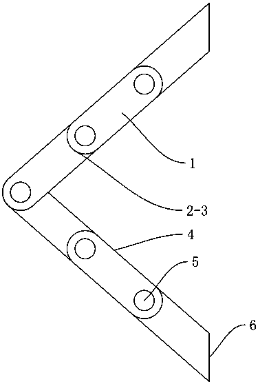
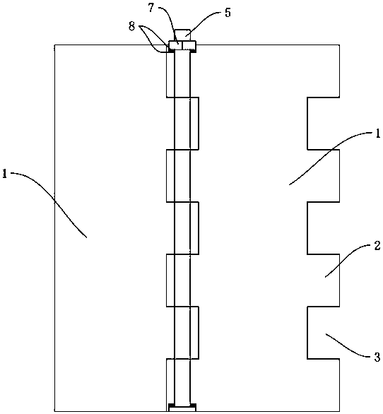
[0033] Embodiment 1: a kind of novel locking pipe (see figure 1 image 3 ), the whole is a foldable structure in which a plurality of rectangular slats 1 are hinged to each other through high-strength connecting shafts 5. There are 6 slats in this embodiment, and four of them have connecting structures on both sides , two of them have only one side with a connecting structure, and the other side is a straight edge 6, and the two strips are located on both sides of the lock pipe. The slats are hinged by the connecting shaft and then locked by the locking device to form a shape suitable for the end face of the wall section. The slats have a contact plane 4 . The straight edge and the contact plane are non-perpendicular, and the straight edge and the contact plane form an angle of 45°.

[0034]The slats are integrally structured along the length direction, the length of the slats is equal to the length of the lock pipe, the sides of the slats are respectively provided with conc...

Embodiment 2

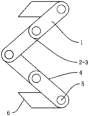
[0037] Embodiment 2: a kind of novel locking pipe (referring to figure 2 ), the difference from Example 1 is that when adjusting the width of the locking tube, the outermost slats can be rotated around the connecting shaft to form an M-shaped structure, which also maintains a suitable clip between the two contact planes corners, and the height of the protruding sharp corner at the end of the wall segment will not be very high. Refer to Example 1 for all the other structures.

Embodiment 3

[0038] Embodiment 3: a kind of novel locking pipe (referring to Figure 7 ), the difference from Example 1 is that the lock pipe is formed as a whole in a trapezoidal shape, the middle two of the six slats are on the same plane, and the two panels on both sides are on the same plane respectively, and the remaining structures refer to the embodiment 1.


PUM


Abstract

The invention relates to a novel fore shaft pipe. The problems that rigid round steel pipe are adopted as existing fore shaft pipes, the diameters cannot change along with the widths of continuous walls, the fore shaft pipes need to be prepared according to the widths of the different continuous walls, and adaptability is poor are solved. The novel fore shaft pipe is of a foldable structure overall and comprises a plurality of sections of strip plates with enough thicknesses, and the strip plates are connected through high-strength connecting shafts. Locking devices are arranged between corresponding strip plates. The strip plates are provided with contact planes. The strip plates rotate and adjust to the fore shaft width equal to the width of the continuous wall around the connecting shafts, the strip plates rotate around the connecting shafts, and the closed shape of the end of a wall section is changed. The whole fore shaft pipe forms the foldable structure, the occupied space can be reduced after folding, transport is convenient, the width of the fore shaft pipe can also be changed through folding, thus the fore shaft pipe adapts to building of underground continuous walls of different widths, the width of the fore shaft pipe is adjusted freely, adaptability is good, and the fore shaft pipe is easier to place and can be reused.

Description

technical field [0001] The invention belongs to the field of underground continuous wall construction, in particular to a novel locking pipe. Background technique [0002] The underground diaphragm wall is a kind of trenching machine used on the ground for basic engineering. Along the peripheral axis of the deep excavation project, a long and narrow deep trench is excavated under the condition of mud retaining wall. After the trench is cleaned, it is hung in the trench Reinforcement cages, and then use the conduit method to pour underwater concrete to form a unit trough section. In this way, a continuous reinforced concrete wall is built underground as a water interception, anti-seepage, load-bearing, and water-retaining structure. Before the trench section is excavated, the guide wall is constructed along the longitudinal axis of the continuous wall, and is poured with cast-in-place concrete or reinforced concrete. The underground diaphragm wall is composed of many wall se...

Claims


Application Information

Patent Timeline
Patent Type & Authority Applications(China)
IPC IPC(8): E02D5/18
CPCE02D5/187
Inventor 段诺刘念武俞峰刘帅段超远
Owner ZHEJIANG SCI-TECH UNIV
Why Eureka
Try Eureka