Slanting backward type road shoulder wall back drainage system and construction method

A technology for drainage system and road shoulder, which is applied in the field of drainage system behind inclined road shoulder wall, which can solve the problems of increased load, increased saturated area of ​​sliding body, damage, etc., and achieves the effect of convenient and fast construction and easy quality

Inactive Publication Date: 2018-12-21
WISDRI ENG & RES INC LTD +1
View PDF5 Cites 12 Cited by
  • Summary
  • Abstract
  • Description
  • Claims
  • Application Information

AI Technical Summary

Problems solved by technology

Generally, the drainage behind the shoulder wall only depends on the drainage pipes arranged at certain distances on the retaining wall body. This method usually has the following problems: 1) There is no filtering structure behind the retaining wall, and the drainage pipes are easily damaged by soil during long-term use. The blockage will lead to poor drainage behind the wall. With the infiltration of rainwater and the sudden rise of the groundwater level, the saturated area of ​​the potential sliding body will suddenly increase, resulting in a decrease in the stability coefficient of the retaining wall, which will eventually lead to increased deformation of the retaining wall and slippage destroy
2) A crushed stone filter layer is installed behind the retaining wall, but they are simply laid out according to the standard or based on experience, without considering the actual construction quality. water, resulting in increased loads behind the wall, greatly reducing the stability of the retaining wall structure

Method used


Image

  • Slanting backward type road shoulder wall back drainage system and construction method
  • Slanting backward type road shoulder wall back drainage system and construction method
  • Slanting backward type road shoulder wall back drainage system and construction method

Examples


Embodiment 1

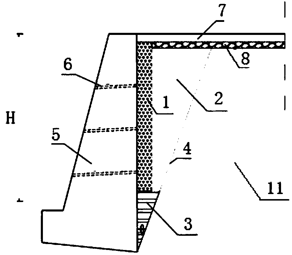
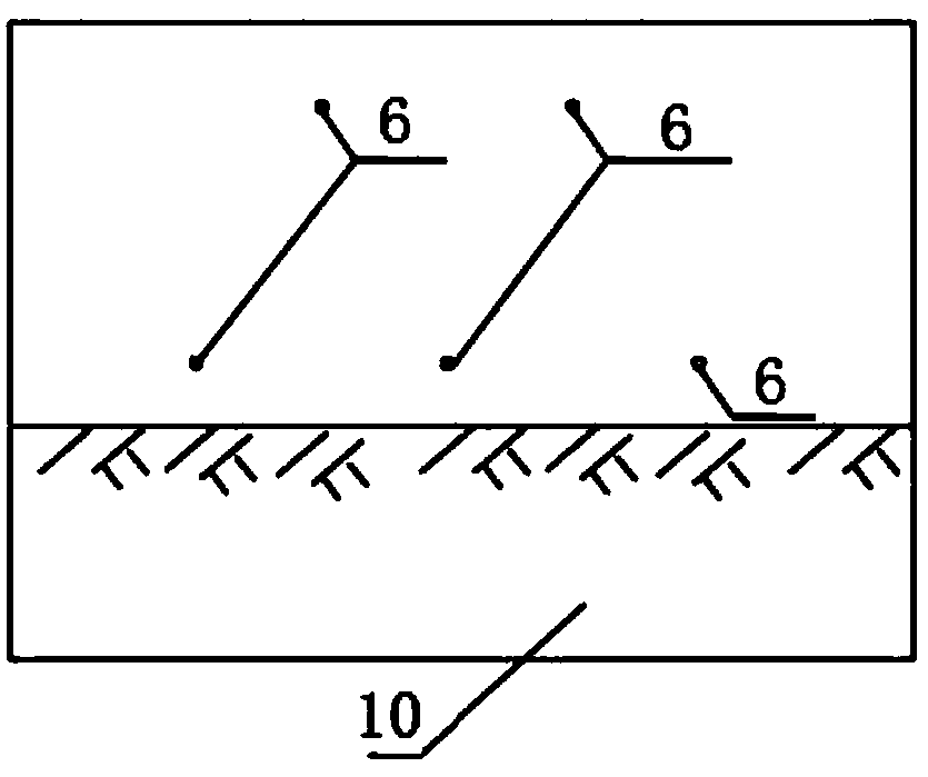
[0076] Example 1, see figure 1 , Figure 3-Figure 6 , a drainage system behind an inclined road shoulder wall, which includes a gravel or pebble filter layer 1, a water-permeable material 2, a permeable geotextile 4, a drain pipe 6, and a graded gravel subbase 8. The gravel or pebble filter layer 1 has a width of 30 cm and is placed inside the retaining wall 5 . The upper part is the pavement structure layer 7 and the lower part is the cohesive soil 3 . The permeable material 2 is mainly composed of medium-coarse sand, wrapped by a composite geomembrane, placed between the gravel or pebble filter layer 1 and the backfill roadbed 11, and has an inverted right-angled triangle structure, with one vertical side close to the graded gravel subbase 8. The other vertical side is close to the inner side of the retaining wall 5, that is, the water-permeable material 2 gradually increases from bottom to top. The permeable geotextile 4 is arranged along the side slope of the backfill ro...

Embodiment 2

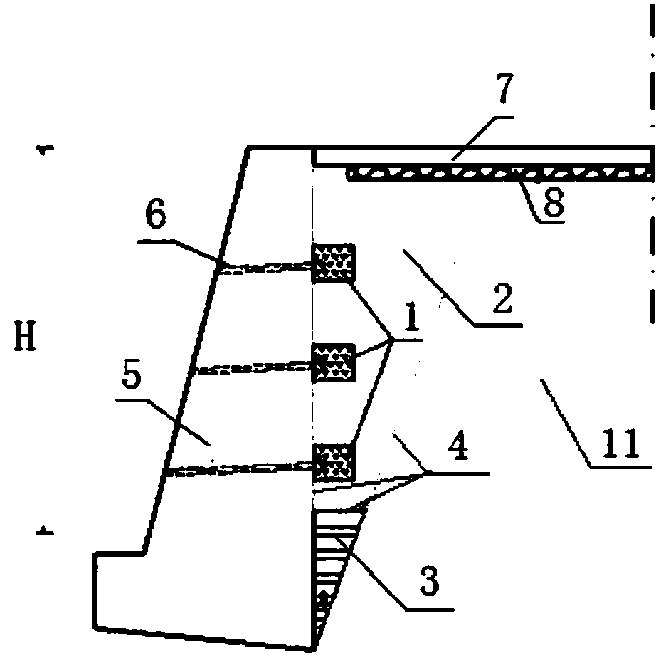
[0098] Example 2, see Figure 2-Figure 6 , a drainage system behind an inclined road shoulder wall, which includes a gravel or pebble filter layer 1, a water-permeable material 2, a permeable geotextile 4, a drain pipe 6, and a graded gravel subbase 8. There are multiple gravel or pebble filter layers 1, which are placed inside the retaining wall 5 and are located at the drain holes respectively. The permeable material 2 is mainly composed of medium-coarse sand, wrapped by a composite geomembrane, placed between the retaining wall 5 and the backfill roadbed 11, and has an inverted right-angled triangle structure, one vertical side is close to the graded crushed stone subbase 8, and the other is vertical The side is close to the inner side of the retaining wall 5, that is, the water-permeable material 2 gradually increases from bottom to top. The gravel or pebble filter layer 1 is embedded on the water-permeable material 2; the water-permeable geotextile 4 is arranged along th...


PUM


Abstract

The invention discloses a slanting backward type road shoulder wall back drainage system. The slanting backward type road shoulder wall back drainage system comprises a broken stone or cobble invertedfilter layer, a water-permeable material, water-permeable geotechnical cloth, a plurality of water drain pipes and a graded broken stone sub-base layer. The broken stone or cobble inverted filter layer is arranged on the inner side of a retaining wall. The water-permeable material is arranged between the broken stone or cobble inverted filter layer and a backfilling subgrade and is of an invertedtriangle structure. The water-permeable geotechnical cloth is arranged along a backfilling subgrade slope, the bottom of the retaining wall and the inner side wall body of the retaining wall. The water drain pipes are arranged in water drain holes in the retaining wall, one ends of the water drain pipes communicate with the broken stone or cobble inverted filter layer, the other ends of the waterdrain pipes are placed on the outer side of the retaining wall, and the water drain pipes are used for draining water on the inner side of the retaining wall. The graded broken stone sub-base layer is placed under a pavement structure layer and on the water-permeable material and the backfilling subgrade. The invention further provides a construction method of the slanting backward type road shoulder wall back drainage system. Through the slanting backward type road shoulder wall back drainage system and the construction method, the water on the back of the subgrade retaining wall can be drained, and the stability of the subgrade and the road shoulder retaining wall is ensured.

Description

technical field [0001] The invention relates to the field of retaining wall drainage, in particular to a drainage system and a construction method behind an inclined road shoulder wall. Background technique [0002] In subgrade engineering, it is often necessary to set shoulder walls as subgrade structures in the filling section of the subgrade to ensure the stability of the subgrade and the integrity of the road surface, while reducing earthwork and land occupation and preventing water erosion. It is often used to treat subgrade diseases such as landslides and landslides. At present, our country is in a period of rapid development, and a large number of slope support structures are built every year. The retaining wall is the most common one. If there is a problem with the retaining wall, it will have a great impact on the stability and safety of the subgrade. [0003] The instability and failure of retaining walls of subgrades are often related to groundwater, and currently...

Claims


Application Information

Patent Timeline
Patent Type & Authority Applications(China)
IPC IPC(8): E02D29/02E02D19/12
CPCE02D19/12E02D29/02
Inventor 赵乾文程小亮
Owner WISDRI ENG & RES INC LTD
Why Eureka
Try Eureka