Multifunctional replaceable coupling beam structure

A multi-functional, connecting beam technology, applied in truss structures, joists, girders, etc., can solve problems such as poor displacement control effect, shear damage, and insignificant improvement, and avoid post-earthquake repair and reinforcement costs. , Improve the ability of rapid recovery, and facilitate the effect of promotion and application

Active Publication Date: 2018-12-21
TONGJI UNIV
View PDF12 Cites 6 Cited by
  • Summary
  • Abstract
  • Description
  • Claims
  • Application Information

AI Technical Summary

Problems solved by technology

At present, there are some defects in the design of the coupling beam: (1) The span height of the coupling beam in the actual project is relatively small, and it is prone to shear failure under the action of the earthquake, forming X-shaped cross cracks
It is difficult to repair after the earthquake. Even if it can be repaired, the repair cost is relatively high and the construction period is long, which affects the rapid recovery of building functions after the earthquake, and thus brings unpredictable indirect economic losses.
(2) The coupling beam with viscoelastic damper has obvious improvement effect under the action of wind vibration and small earthquake, but the improvement effect is not obvious under the action of large earthquake
(3) The connecting beam with additional composite damper (composed of viscoelastic rubber and U-shaped steel plate), due to the small stiffness of the damper, the displacement control effect is not good
(4) For metal dampers with diamond-shaped openings, the stress concentration at the openings leads to premature cracking

Method used


Image

  • Multifunctional replaceable coupling beam structure
  • Multifunctional replaceable coupling beam structure
  • Multifunctional replaceable coupling beam structure

Examples


Embodiment 1

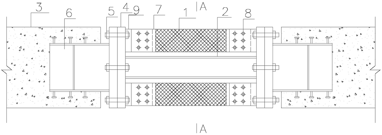
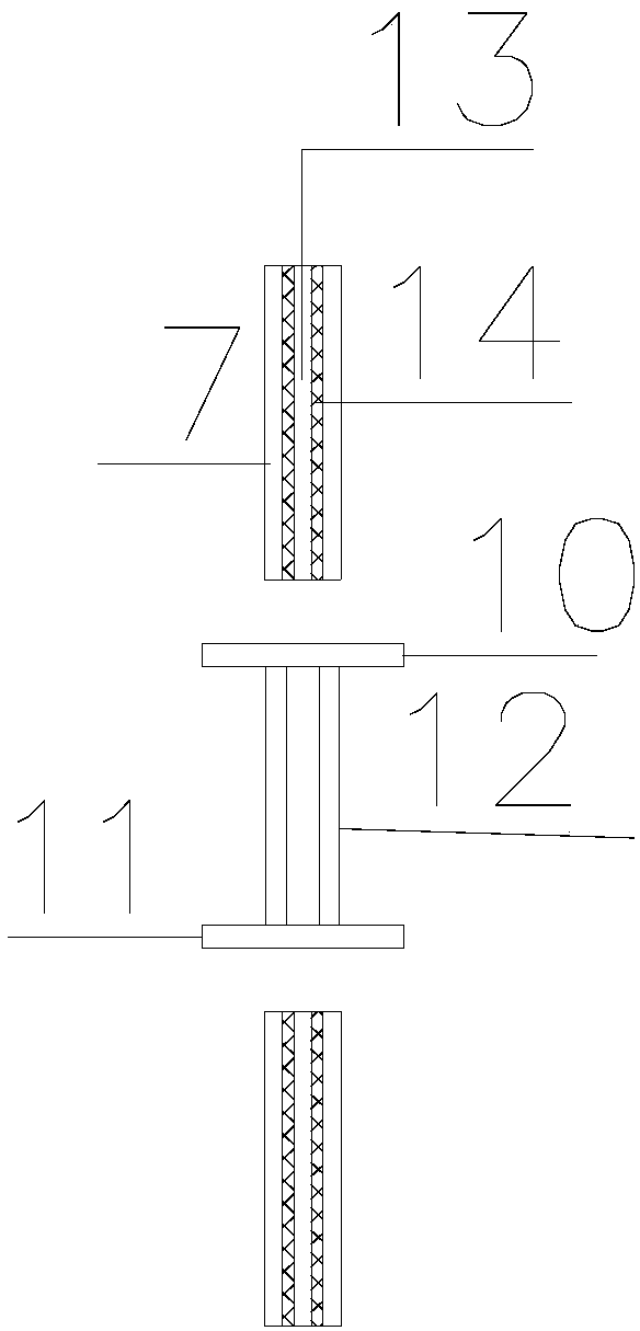
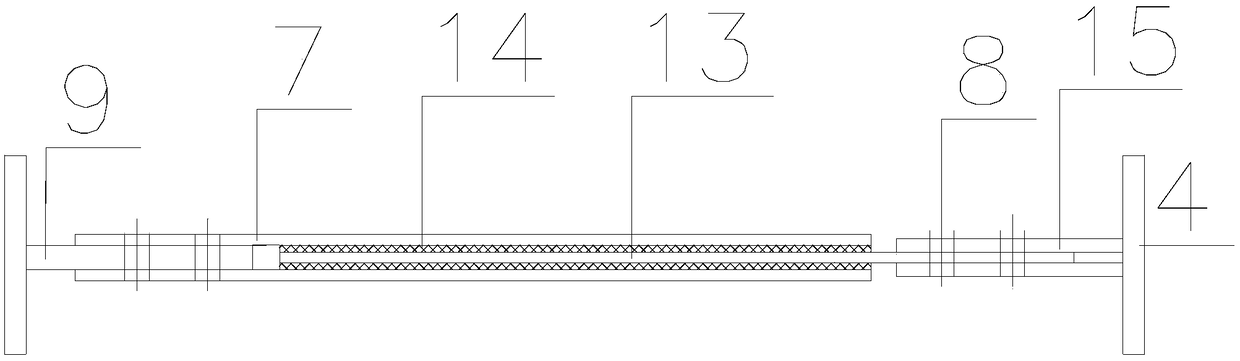
[0026] Such as figure 1 and 2 As shown, the new replaceable connecting beam structure with a composite damper of the present invention includes a viscoelastic damper 1, a metal damper 2, a non-replaceable section 3 and an embedded part 6. The metal damper 2 is composed of an upper flange 10, a lower flange 11 and a plurality of parallel webs 12. The webs are made of steel with a low yield point, and the flanges 10 and 11 are welded together with the webs. Lower shear yield energy dissipation. The viscoelastic damper is composed of rubber layer 14, inner steel plate 13 and outer steel plate 7, which can dissipate energy under the action of wind vibration and small earthquake. The metal damper 2 and the viscoelastic damper 1 are connected in parallel and welded with the end plate 4 . The bending strength and shear strength of the non-replacement section 3 are greater than those of the composite damper, ensuring that the non-replacement section does not yield under the action ...


PUM


Abstract

The invention relates to a multifunctional replaceable coupling beam structure. The coupling beam structure comprises a replaceable segment and non-replaceable segments which are connected at two endsof the replaceable segment in a detachable mode, the replaceable segment consists of a viscoelastic damper and a metal damper which are connected in parallel, wherein the viscoelastic damper consistsof steel plate layers and rubber layers which are alternately distributed between the steel plate layers, the metal damper is an 'H'-like steel part consisting of a top flange, a bottom flange and aweb welded between the top flange and the bottom flange, the viscoelastic damper can dissipate energy in wind-induced vibration and small earthquake transformation, the metal damper shears yielding energy dissipation under the action of a medium earthquake and a major earthquake, the replaceable coupling beam has both wind-resistant and earthquake-proof functions, is strong in energy dissipation capacity and can be quickly replaced after an earthquake.

Description

technical field [0001] The invention relates to the technical field of recoverable functional structures, in particular to a multifunctional replaceable connecting beam structure. Background technique [0002] In shear wall structures and frame-shear wall structures, the beams connected to the shear walls at both ends are called coupling beams. Coupling beams are the main energy-dissipating components in shear wall structures under earthquake action. At present, there are some defects in the design of coupling beams: (1) The span height of coupling beams in actual engineering is relatively small, which is prone to shear failure under earthquake action, forming X-shaped cross cracks. For example, in the Wenchuan earthquake and Chile earthquake, a large number of connecting beams were severely damaged. It is difficult to repair after the earthquake. Even if it can be repaired, the repair cost is high and the construction period is long, which affects the rapid recovery of bu...

Claims


Application Information

Patent Timeline
Patent Type & Authority Applications(China)
IPC IPC(8): E04C3/04E04B1/98E04H9/02
CPCE04C3/04E04H9/021
Inventor 蒋欢军李书蓉
Owner TONGJI UNIV
Why Eureka
Try Eureka