
Single-cylinder spiral airflow engine

A technology of spiral airflow and engine, which is applied to engine components, machines/engines, non-variable-capacity engines, etc., can solve the problems of low engine efficiency, pollute the environment, and low function conversion efficiency, achieve high efficiency, ensure safety performance, The effect of delaying the ignition and detonation cycle

Active Publication Date: 2018-12-21
郑彤
View PDF5 Cites 1 Cited by
  • Summary
  • Abstract
  • Description
  • Claims
  • Application Information

AI Technical Summary

Problems solved by technology

[0004] It can be seen from this that whether it is a two-stroke engine or a four-stroke engine, in terms of its working principle, its function conversion efficiency is low, only part of the stroke is doing work, and the remaining strokes complete the intake, gas compression and exhaust. Without work, the efficiency of the engine is low, the limit value of the speed is small, and the volume of the multi-cylinder multi-stroke setting is large
The gas emitted by traditional engines can only be exhaust gas, which can neither do work nor be recovered, and also pollute the environment, which can be said to be harmful but not beneficial

Method used

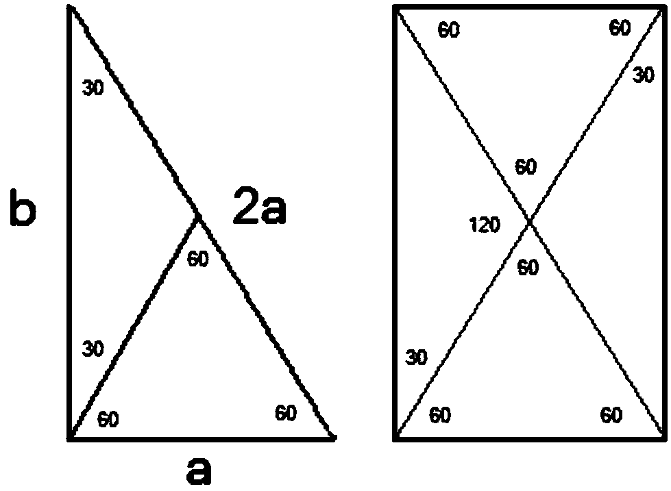
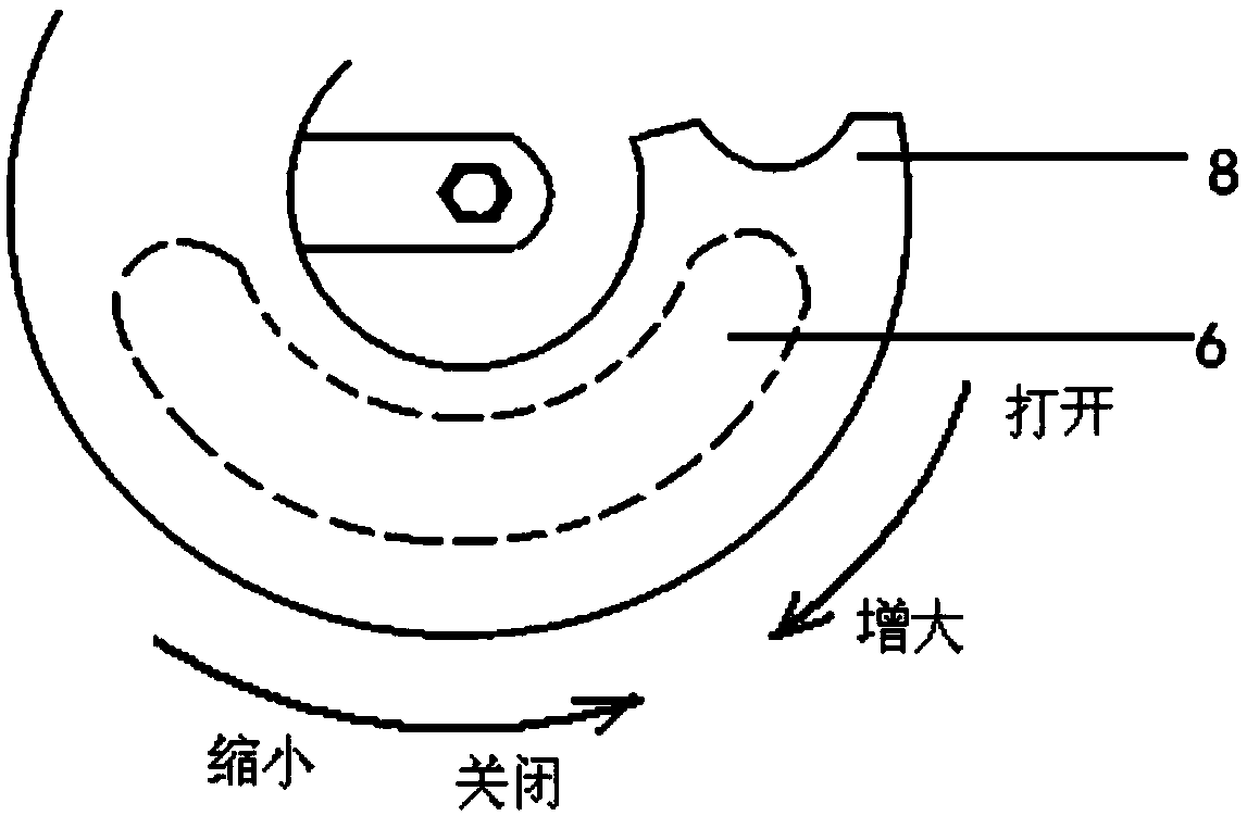

Image

  • Single-cylinder spiral airflow engine
  • Single-cylinder spiral airflow engine
  • Single-cylinder spiral airflow engine

Examples


Embodiment Construction

[0031] The present invention will be further described in detail below in conjunction with the accompanying drawings, so that those skilled in the art can implement it with reference to the description.

[0032] It should be understood that terms such as "having", "comprising" and "including" as used herein do not entail the presence or addition of one or more other elements or combinations thereof.

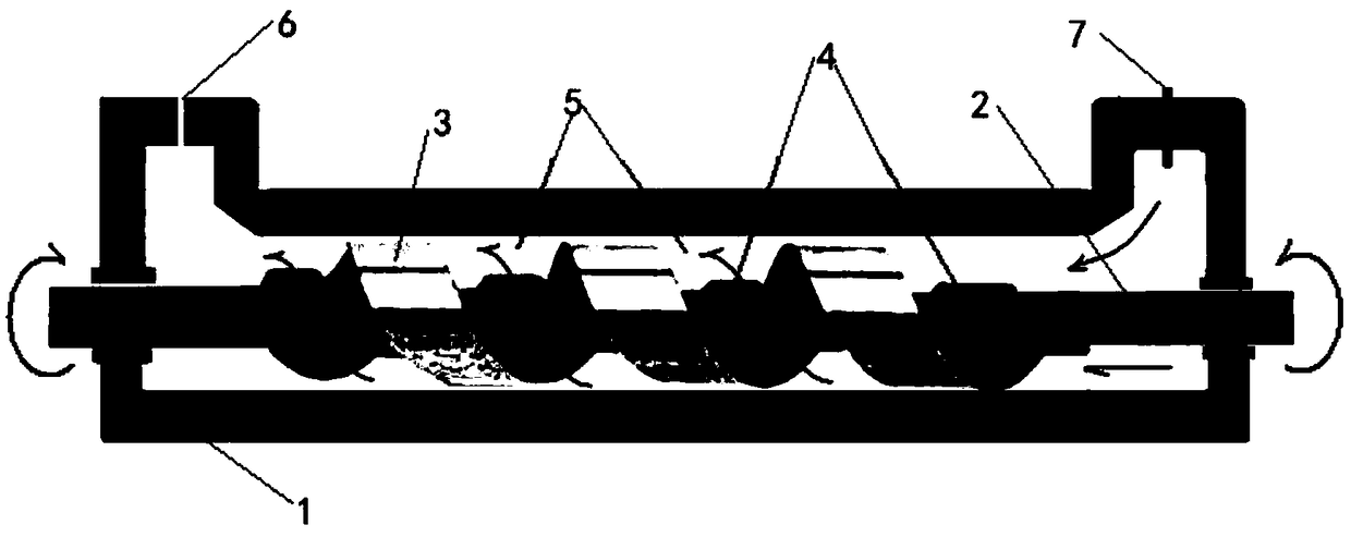
[0033] Such as figure 1 and Figure 6 Shown, the invention provides a kind of single-cylinder helical flow engine, comprising:

[0034] The cylinder block 1 and the cylinder shaft 2 arranged along the axis of the cylinder block, the helical impeller 3 spirally arranged along the circumference of the cylinder shaft 2, and the spiral impeller 3, the inner wall of the cylinder block 1 and the cylinder shaft 2 define a directional spiral air flow channel 5;

[0035] The resistance protrusion 4 is arranged on the cylinder shaft 2 and is located in the spiral air flow passage 5, and ...


PUM


Abstract

The invention discloses a single-cylinder spiral airflow engine. The single-cylinder spiral airflow engine comprises a cylinder body, a cylinder shaft, resistance bulges, an oil nozzle and an exhausthole, wherein the cylinder shaft is arranged along the axis of the cylinder body, a spiral impeller is spirally arranged along the circumference of the cylinder shaft, and a directional spiral airflowchannel is defined between the spiral impeller and the inner wall of the cylinder body and the cylinder shaft; the resistance bulges are arranged on the cylinder shaft and are positioned in the spiral air flow channel, and extend in the radial direction of the cylinder shaft from the periphery of the cylinder shaft; and the oil nozzle and the exhaust hole are respectively arranged at the two endsof the cylinder body, a combustion chamber is arranged at one end, close to the oil nozzle, of the oil nozzle, one end, close to the exhaust hole, of the ignition device is an exhaust chamber, the oil nozzle is connected with an oil tank, an ignition device at the position of the oil nozzle is ignited, and the high-pressure spiral airflow generated after blasting drives the resistance bulges andthe cylinder shaft to rotate. The single-cylinder spiral airflow engine has the advantages that the principle is simple, the structure is simple, the manufacture is easy, the manufacturing cost is low, materials are saved, the weight is light, fuel is saved, the pollution is little, the size is small, the speed change is high, the speed is high, the speed per hour can reach more than 400 kilometers, and a complex mechanism such as a gearbox and the like is not needed.

Description

technical field [0001] The present invention relates to a new type of engine. More specifically, the present invention relates to a single cylinder helical flow engine. Background technique [0002] An engine is a machine that can convert other forms of energy into mechanical energy. Traditionally, engines include internal combustion engines, external combustion engines, and electric motors. An engine can refer to either a power generating device or the entire machine including the power device. The engine was first born in the UK, so the concept of the engine also originated from English, and its original meaning refers to the kind of "mechanical device that generates power". [0003] At present, known and available generators on the market have no more than two working principles, two-stroke engine and four-stroke engine working principle. The working principle of the two-stroke engine is: there are three holes on the cylinder of the engine, which are the air intake hol...

Claims


Application Information

Patent Timeline
Patent Type & Authority Applications(China)
IPC IPC(8): F02C3/14F02C6/20F02C7/22F02C7/224F02C3/22F01D1/38F01D25/30
CPCF01D1/38F01D25/30F02C3/14F02C3/22F02C6/20F02C7/22F02C7/224
Inventor 郑彤
Owner 郑彤
Learn More