Method and device capable of preventing cooler butterfly valve from being tightly closed

A technology of coolers and butterfly valves, which is applied in the direction of valve heating/cooling devices, valve devices, valve lifts, etc., can solve problems such as unfavorable valve stem stability, unsatisfactory use effect, troublesome maintenance, etc., to improve convenience and Stability, ensuring safety and high efficiency, easy to disassemble and replace

Pending Publication Date: 2018-12-21
东营市科德化工有限公司
View PDF0 Cites 3 Cited by
  • Summary
  • Abstract
  • Description
  • Claims
  • Application Information

AI Technical Summary

Problems solved by technology

[0002] During the use of the maleic anhydride plant in the n-butane oxidation method, it is necessary to connect a large-diameter cooler through a butterfly valve for output control. However, there are some problems in the actual use process. For example, the valve uses a jacketed insulating butterfly valve. Due to the characteristics of maleic anhydride, After the butterfly valve of the standby cooler is closed, maleic anhydride solids will accumulate on the butterfly valve plate, causing the valve to fail to open and close, and affecting the stability of use. At the same time, most of the existing butterfly valve structures directly install the valve plate to the valve shell through the shaft. Inside the body, and because the shaft is straight from the upper end to the lower end, not only the length of the connection with the valve plate is relatively large, which is not conducive to passing through, but also it is not convenient to disassemble and replace the valve plate, the maintenance is more troublesome, and the locking structure of the butterfly valve is relatively Single, poor structural stability, not conducive to maintaining the stability of the valve stem, the use effect is not ideal

Method used


Image

  • Method and device capable of preventing cooler butterfly valve from being tightly closed
  • Method and device capable of preventing cooler butterfly valve from being tightly closed
  • Method and device capable of preventing cooler butterfly valve from being tightly closed

Examples


Embodiment Construction

[0020] The following will clearly and completely describe the technical solutions in the embodiments of the present invention with reference to the accompanying drawings in the embodiments of the present invention. Obviously, the described embodiments are only some of the embodiments of the present invention, not all of them. Based on the embodiments of the present invention, all other embodiments obtained by persons of ordinary skill in the art without making creative efforts belong to the protection scope of the present invention.

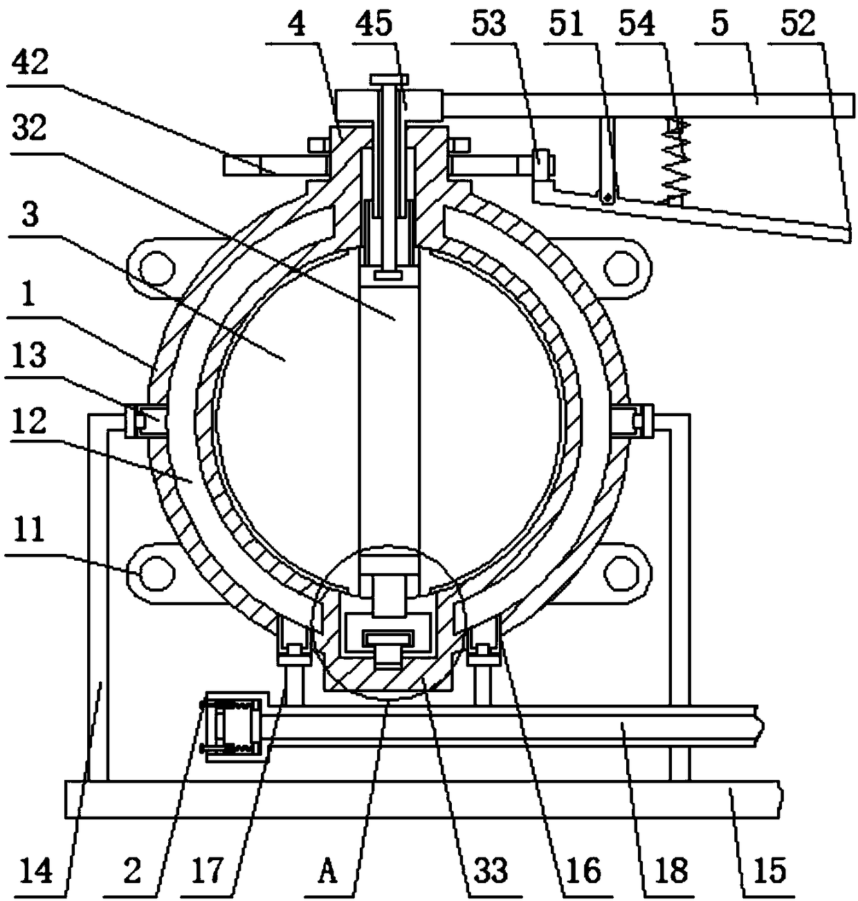
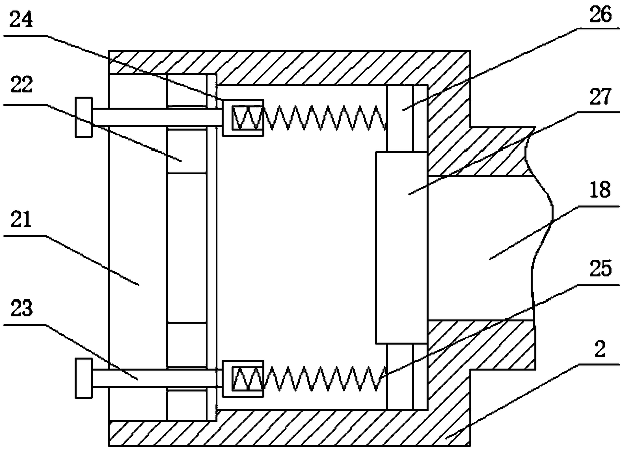
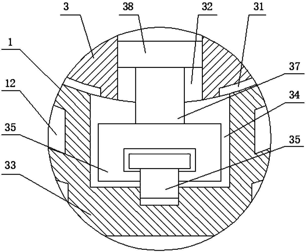
[0021] see Figure 1-5 , the present invention provides a technical solution: a method and device for preventing the butterfly valve of the cooler from being closed, including a valve housing 1, and mounting flanges 11 are provided on both sides of the outer surface of the valve housing 1 to facilitate the connection of both ends The pipeline and the cooler are fixed and installed by bolts, which is more convenient and stable. There are cavities ...


PUM


Abstract

The invention discloses a method and device capable of preventing a cooler butterfly valve from being tightly closed. The device comprises a valve shell, and the both sides of the outside surface of the valve shell are each provided with a mounting flange; the both sides of the inner wall of the valve shell are each provided with a cavity, and the upper sides of the two ends of the outside surfaceof each cavity are provided with air inlet connectors; the inside surface of each air inlet connector is in threaded connection with an air inlet connecting pipe of which the other end is fixedly provided with an air inlet main pipe; the both sides of the lower surface of each cavity are each provided with an air outlet connector of which the inside surface is in threaded connection with an air outlet connecting pipe, and the other end of each air outlet connecting pipe is fixedly connected to an air outlet main pipe; and the front end surface of the air outlet main pipe is fixedly connectedto a regulating pipe. According to the method and device capable of preventing the cooler butterfly valve from being tightly closed, through arrangement of the cavities in the valve shell, the use convenience and stability can be improved greatly, and the safety and efficiency are ensured.

Description

technical field [0001] The invention relates to the technical field of butterfly valves, in particular to a method and device for preventing the butterfly valve of a cooler from being closed. Background technique [0002] During the use of the maleic anhydride plant in the n-butane oxidation method, it is necessary to connect a large-diameter cooler through a butterfly valve for output control. However, there are some problems in the actual use process. For example, the valve uses a jacketed insulating butterfly valve. Due to the characteristics of maleic anhydride, After the butterfly valve of the standby cooler is closed, maleic anhydride solids will accumulate on the butterfly valve plate, causing the valve to fail to open and close, and affecting the stability of use. At the same time, most of the existing butterfly valve structures directly install the valve plate to the valve shell through the shaft. Inside the body, and because the shaft is straight from the upper end...

Claims


Application Information

Patent Timeline
Patent Type & Authority Applications(China)
IPC IPC(8): F16K49/00F16K27/02F16K1/22F16K17/04F16K51/00F16K1/32
CPCF16K49/005F16K1/221F16K1/224F16K1/32F16K17/0413F16K27/0218F16K51/00
Inventor 王春刚杨眉
Owner 东营市科德化工有限公司
Why Eureka
Try Eureka