
Variable frequency electromagnetic boiler

A boiler and electromagnetic technology, applied in the field of frequency conversion electromagnetic boiler, can solve the problems of electric boiler heating technology is not very mature, short service life, large maintenance, etc., to achieve the effect of good insulation, no maintenance costs, long life

Pending Publication Date: 2018-12-21
于永年
View PDF0 Cites 0 Cited by
  • Summary
  • Abstract
  • Description
  • Claims
  • Application Information

AI Technical Summary

Problems solved by technology

[0002] The existing electric boiler heating technology is not very mature, and has the following disadvantages: large heat loss, the traditional electric heating industry generally adopts electric heating rods and electrode methods, and this traditional heating method has relatively low thermal efficiency, electric heating rods And the electrode mainly relies on electricity, self-heating and then transferring heat to the liquid, so as to heat the liquid. The heat utilization rate of this heating effect is only about 50%-80%, and the heat loss is as high as 20%- More than 50%; short service life: large amount of maintenance
The electric heating tube is easy to burn out due to high temperature aging due to the use of electric heating rods and electrodes to generate heat
As a result, fire or electric shock accidents are caused, the service life is short, the thermal efficiency is low, and it decays year by year

Method used


Image

  • Variable frequency electromagnetic boiler
  • Variable frequency electromagnetic boiler
  • Variable frequency electromagnetic boiler

Examples


Embodiment 1

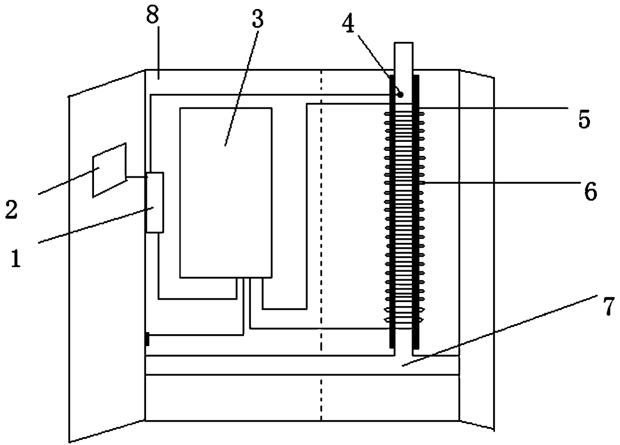
[0015] Such as figure 1 , 2 As shown, the present invention discloses a variable frequency electromagnetic boiler, which includes a furnace body 8, a metal pipe 7, a coil 6, an insulating layer 5, a temperature control probe 4, a frequency converter 3, a control module 1, and a display screen 2 , the display screen 2 is connected to the control module 1, the control module 1 is connected to the frequency converter 3 and the temperature control probe 4, the frequency converter 3 is connected to the coil 6, the inner layer of the coil is an insulating layer 5, and the insulating layer 5 is wrapped with a metal pipe 7, all The outermost layer of the accessories is the furnace body 8, and liquid is arranged in the metal pipe.

Embodiment 2

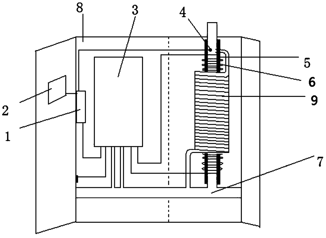
[0017] image 3 It is a schematic diagram of double-barrel heating of a frequency conversion electromagnetic boiler high temperature coil in the present invention, as shown in image 3 As shown, the present invention discloses a frequency conversion electromagnetic boiler. The difference from Embodiment 1 is that a second layer of metal pipes 9 is arranged outside the coil.

[0018] The second layer of metal pipe 9 is hollow and spirally wound outside the coil 6, and the liquid in the two layers of pipes communicates; the frequency converter 3 in Embodiment 2 is water-cooled.

[0019] In the present invention, a plurality of frequency converters can be connected in series or in parallel to form a group, the frequency converters are respectively connected to the coils wrapped in metal pipes, and the metal pipes are connected in series or in parallel.

[0020] The frequency conversion electromagnetic boiler of the present invention is currently unattended, and can achieve remot...


PUM


Abstract

The invention discloses a variable frequency electromagnetic boiler. The variable frequency electromagnetic boiler comprises a boiler body, a metal pipe, a coil, an insulation layer, a temperature control probe, a frequency converter, a control module and a display screen; the display screen is connected with the control module; the control module is connected with the frequency converter and thetemperature control probe; the frequency converter is connected with the coil; an inner layer of the coil is an insulation layer; a pipe is wrapped in the insulation layer; the boiler body is arrangedon the outermost layers of all fittings; and the pipe is filled with liquid. The variable frequency electromagnetic boiler achieves high efficiency, energy conservation, long life, safety, reliability, accurate temperature control and excellent insulativity.

Description

technical field [0001] The invention belongs to the technical field of electric heating, in particular to a variable frequency electromagnetic boiler. Background technique [0002] The existing electric boiler heating technology is not very mature, and has the following disadvantages: large heat loss, the traditional electric heating industry generally adopts electric heating rods and electrode methods, and this traditional heating method has relatively low thermal efficiency, electric heating rods And the electrode mainly relies on electricity, self-heating and then transferring heat to the liquid, so as to heat the liquid. The heat utilization rate of this heating effect is only about 50%-80%, and the heat loss is as high as 20%- More than 50%; short service life: large amount of maintenance. The electric heating tube is easy to burn out due to high temperature aging due to the use of electric heating rods and electrodes to generate heat. As a result, fire or electric sh...

Claims


Application Information

Patent Timeline
IPC IPC(8): F24D13/04F24D19/10F24H1/40F24H9/18F24H9/20
CPCF24D13/04F24D19/1096F24H1/40F24H9/1818F24H9/2014
Inventor 于永年
Owner 于永年
Learn More