Tightening instrument for power transmission and distribution lines
A technology of transmission and distribution lines and wire tightening instruments, which is applied in the direction of instruments, electromagnetic measuring devices, force/torque/power measuring instruments, etc., can solve the problems such as difficulty in determining whether the degree of wire tightening is in place, and achieve accurate and convenient tension values at the hanging points. The effect of using and saving operation time
- Summary
- Abstract
- Description
- Claims
- Application Information
AI Technical Summary
Problems solved by technology
Method used
Image
Examples
Embodiment 1
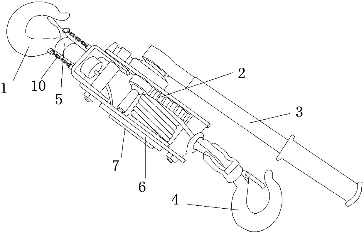
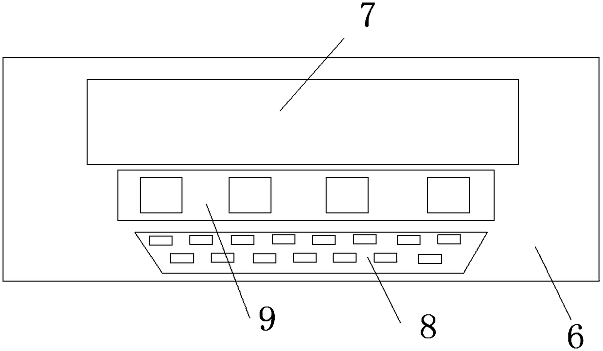
[0048] A wire tensioner for transmission and distribution lines, comprising a body of the wire tensioner, the body of the wire tensioner includes a positioning hook 1, a tightening gear 2, a handle 3, and a pull hook 4, and the positioning hook 1 is connected to the retractor through a column resistance sensor One end of the tightening gear 2, the drag hook 4 is connected to the other end of the tightening gear 2 through a twisted wire, and the handle 3 drives the tightening gear 2 to rotate; the column resistance sensor is connected with a dynamic resistance strain gauge 6, and the dynamic resistance strain gauge 6 is provided with Rally display module7.
[0049] The body of the wire tensioner is the prior art, the positioning hook 1 is used to fix the body of the wire tensioner, the pull hook 4 pulls the wire to be tightened, the handle 3 drives the tightening gear 2 to rotate, and the tightening gear 2 pulls the pull hook 4 through the stranded wire Thus tightening the line. ...
Embodiment 2
[0051] A wire tensioner for transmission and distribution lines, comprising a body of the wire tensioner, the body of the wire tensioner includes a positioning hook 1, a tightening gear 2, a handle 3, and a pull hook 4, and the positioning hook 1 is connected to the retractor through a column resistance sensor One end of the tightening gear 2, the drag hook 4 is connected to the other end of the tightening gear 2 through a twisted wire, and the handle 3 drives the tightening gear 2 to rotate; the column resistance sensor is connected with a dynamic resistance strain gauge 6, and the dynamic resistance strain gauge 6 is provided with The tension display module 7 and the dynamic resistance strain gauge 6 are also sequentially connected with an input module 8, a single-chip microcomputer that compares the measured value of the column resistance sensor with the input value of the input module 8, and a tension reminder module 9. The tension reminder module 9 includes a signal convers...
Embodiment 3
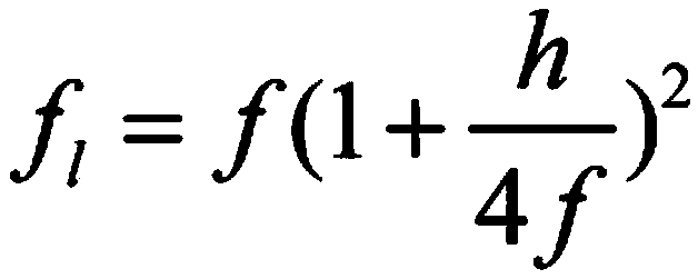
[0054] A wire tensioner for transmission and distribution lines, comprising a body of the wire tensioner, the body of the wire tensioner includes a positioning hook 1, a tightening gear 2, a handle 3, and a pull hook 4, and the positioning hook 1 is connected to the retractor through a column resistance sensor One end of the tightening gear 2, the drag hook 4 is connected to the other end of the tightening gear 2 through a twisted wire, and the handle 3 drives the tightening gear 2 to rotate; the column resistance sensor is connected with a dynamic resistance strain gauge 6, and the dynamic resistance strain gauge 6 is provided with The tension display module 7 and the dynamic resistance strain gauge 6 are also sequentially connected with an input module 8, a single-chip microcomputer that compares the measured value of the column resistance sensor with the input value of the input module 8, and a tension reminder module 9. The tension reminder module 9 includes a signal convers...
PUM
 Abstract
Description
Claims
Application Information
 - R&D
- Intellectual Property
- Life Sciences
- Materials
- Tech Scout
- Unparalleled Data Quality
- Higher Quality Content
- 60% Fewer Hallucinations
Browse by: Latest US Patents, China's latest patents, Technical Efficacy Thesaurus, Application Domain, Technology Topic, Popular Technical Reports.
© 2025 PatSnap. All rights reserved.Legal|Privacy policy|Modern Slavery Act Transparency Statement|Sitemap|About US| Contact US: help@patsnap.com


