
Particle field measurement device based on infrared holography

A particle field and infrared technology, applied in the field of infrared holography, can solve problems such as the inability to obtain real information of other particles, achieve high resolution and improve imaging quality

Active Publication Date: 2018-12-21
KUNMING UNIV OF SCI & TECH
View PDF9 Cites 4 Cited by
  • Summary
  • Abstract
  • Description
  • Claims
  • Application Information

AI Technical Summary

Problems solved by technology

However, it is only at the stage of theoretical research, and the actual particle field exists in three-dimensional space, and a large number of particles block and overlap each other. That is to say, if the experimental method described in its literature is used to detect the real particle field , only the particle field information of a certain front section of the particle field can be obtained, but the real information of other particles covered by the front section cannot be obtained, and the information of most particles in the particle field cannot be obtained

Method used


Image

  • Particle field measurement device based on infrared holography

Examples


Embodiment 1

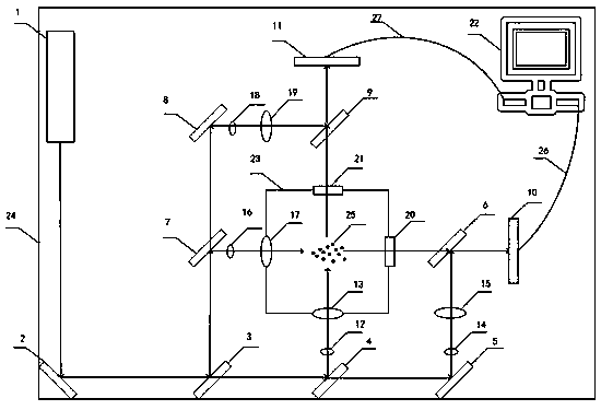
[0024]A device using infrared holography for particle field measurement, including an infrared laser 1, an infrared total reflection mirror I2, an infrared beam splitter I3, an infrared beam splitter II4, an infrared total reflection mirror II5, an infrared beam splitter III6, an infrared beam splitter Beam splitter Ⅳ7, infrared total reflection mirror Ⅲ8, infrared beam splitter Ⅴ9, infrared CCD Ⅰ10, infrared CCD Ⅱ11, infrared beam expander Ⅰ12, infrared collimator Ⅰ13, infrared beam expander Ⅱ14, infrared collimator Ⅱ15, infrared beam expander Mirror Ⅲ16, infrared collimating mirror Ⅲ17, infrared beam expander Ⅳ18, infrared collimating mirror Ⅳ19, germanium flat crystal Ⅰ20, germanium flat crystal Ⅱ21, computer 22, inner shell 23, outer shell 24, particle field to be measured 25, Data line Ⅰ26, data line Ⅱ27, the infrared laser emitted by infrared laser 1 is reflected by the infrared total reflection mirror Ⅰ2 to the infrared beam splitter Ⅰ3, and the infrared beam splitter Ⅰ3...

Embodiment 2

[0032] The structure of this embodiment is the same as that of Embodiment 1, except that:

[0033] The whole device is protected and fixed with an opaque shell, the shell is divided into an inner shell 23 and an outer shell 24, the inner and outer shells are integrated, similar to the square structure of the "back", the inside of the back is empty; The four sides of the inner shell 23 are provided with four round holes, which are respectively embedded with infrared collimating lens I13, infrared collimating lens III17, germanium flat crystal I20, and germanium flat crystal II21, which are respectively used for beam expansion of infrared laser beams. Collimate output, receive and filter out the interference of visible light to improve imaging quality. The infrared laser emitted by the infrared laser 1 is a wave source within the range of 8-13 μm in the infrared atmospheric window band, so as to avoid rapid attenuation when propagating in the air.

[0034] The infrared beam spl...


PUM


Abstract

The invention discloses a particle field measurement device based on infrared holography, and belongs to the field of infrared holographic application. The device comprises an infrared laser, an infrared total reflection mirror I, an infrared beam splitting mirror I, an infrared beam splitting mirror II, an infrared total reflection mirror II, an infrared beam splitting mirror III, an infrared beam splitting mirror IV, an infrared total reflection mirror III, an infrared beam splitting mirror V, an infrared CCD I, an infrared CCD II, an infrared beam expanding mirror I, an infrared collimatingmirror I, an infrared beam expanding mirror II, an infrared collimating mirror II, an infrared beam expanding mirror III, an infrared collimating mirror III, an infrared beam expanding mirror IV, aninfrared collimating mirror IV, germanium flat crystal I and the like. The device disclosed by the invention is used for measuring the particle field, and the three-dimensional full-field distributionof the particle field can be recorded under the condition that an object field is not disturbed, so that the information, such as size, shape, position, speed, acceleration and the like, of the particles can be obtained, and the imaging quality and the detection result of the particle field detection are improved.

Description

technical field [0001] The invention discloses a device using infrared holography for particle field measurement, belonging to the field of infrared holography application. Background technique [0002] In the research of fuel combustion, soot measurement, two-phase flow, droplet breakup, environmental pollution and other fields, laser holography is often used to measure the particle field. Its advantage is that it does not interfere with the object field and can record the three-dimensional particle field. The whole field distribution, so as to obtain the particle size, shape, velocity and acceleration and other information. However, in these engineering research fields, liquid droplets and solid particles have high density and small size, which brings certain difficulties to experimental measurement techniques, such as high density affects light transmittance, and small-sized particles are difficult to distinguish. In previous studies on particle fields, due to the limita...

Claims


Application Information

Patent Timeline
Patent Type & Authority Applications(China)
IPC IPC(8): G01N15/02G01N15/10
CPCG01N15/0205G01N15/10G01N2015/0233
Inventor 刘万里张永安张亚萍潘永峰刘建建
Owner KUNMING UNIV OF SCI & TECH
Learn More