Positioning method and device

A positioning method and positioning algorithm technology, applied in positioning, measuring devices, instruments, etc., can solve the problems of slow system response, large matching calculation, large signal drift, etc., to achieve the effect of improving accuracy

Active Publication Date: 2018-12-21
ZHEJIANG SUPCON TECH
View PDF6 Cites 4 Cited by
  • Summary
  • Abstract
  • Description
  • Claims
  • Application Information

AI Technical Summary

Problems solved by technology

[0002] At present, there are many kinds of wireless signals for indoor or outdoor positioning of process industry factories, such as RFID (Radio Frequency Identification, radio frequency identification technology), low-speed and short-distance communication technology ZigBee, UWB (Ultra Wideband, carrier-free communication technology) and other signals. Two-dimensional positioning, its positioning algorithms mainly include TOA (positioning algorithm based on time of arrival), TDOA (positioning algorithm based on time difference of arrival), AOA (positioning algorithm based on signal angle of arrival), fingerprint positioning algorithm based on RSSI), etc., among them, Algorithms such as TOA and TDOA have high hardware requirements and high cost due to factors such as strict clock synchronization or directional antennas; RSSI-based fingerprint positioning algorithms have large signal drift in the matching database and a large amount of matching calculations, which makes the applicability of the algorithm Weak and slow system response
[0003] Due to the complex characteristics of building layers and metal materials shielding signals in the industrial installation area, there is no mature wireless signal positioning method in the industry that can accurately locate the three-dimensional area. Therefore, how to realize the three-dimensional positioning of the industrial installation area is an important issue For technical personnel in the field, it has become a technical problem to be solved urgently

Method used


Image

  • Positioning method and device
  • Positioning method and device
  • Positioning method and device

Examples


Embodiment Construction

[0057]The following will clearly and completely describe the technical solutions in the embodiments of the present invention with reference to the accompanying drawings in the embodiments of the present invention. Obviously, the described embodiments are only some, not all, embodiments of the present invention. Based on the embodiments of the present invention, all other embodiments obtained by persons of ordinary skill in the art without making creative efforts belong to the protection scope of the present invention.

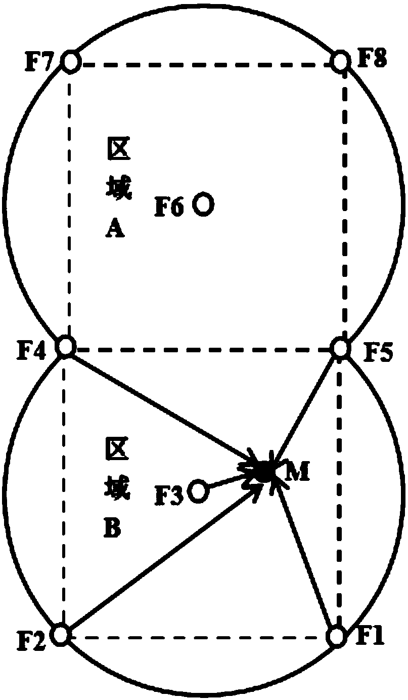
[0058] The positioning method and device provided by the present invention need to divide the industrial device area into positioning areas in advance and deploy low-power Bluetooth tags in each positioning area as positioning tags, and associate the deployed positioning tags with the positioning areas, for example :(F A , (x, y, z), F A-1 , F A-2 , F A-3 ,...,F A-N ), where F A Indicates the A positioning area, (x, y, z) indicates the preset coordinates o...


PUM


Abstract

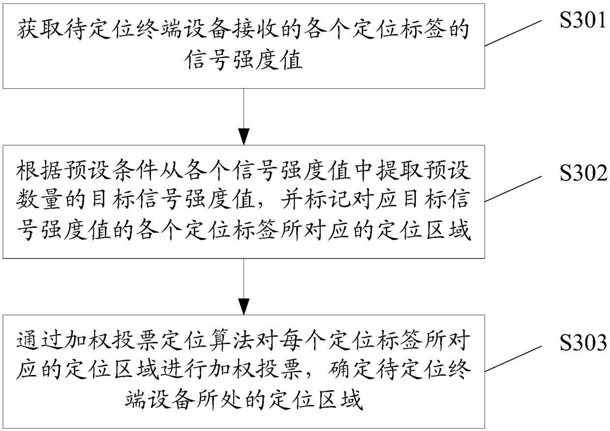
The invention provides a positioning method and a positioning device. The positioning method comprises the following steps that signal intensity values of positioning labels received by terminal equipment to be positioned are obtained; a preset number of target signal intensity values are extracted from the signal intensity values according to a preset condition, and positioning areas corresponding to the positioning labels corresponding to the target signal intensity values are marked; and weighted voting is carried out on the positioning areas corresponding to the positioning labels by a weighted voting positioning algorithm to determine the positioning area in which the terminal equipment to be positioned is located. The positioning method and the positioning device are improved on thebasis of the two-dimensional positioning technology in the prior art, the positioning area in which the terminal equipment to be positioned is located is determined through the weighted voting positioning algorithm, not only positioning in one-dimensional and two-dimensional spaces can be realized, but also three-dimensional positioning on the terminal equipment to be positioned can be performed by expanded to three-dimensional levels, and simultaneously, the accuracy of positioning results is improved.

Description

technical field [0001] The invention relates to the technical field of wireless signal positioning, in particular to a positioning method and device applied to industrial equipment areas. Background technique [0002] At present, there are many kinds of wireless signals for indoor or outdoor positioning of process industry factories, such as RFID (Radio Frequency Identification, radio frequency identification technology), low-speed and short-distance communication technology ZigBee, UWB (Ultra Wideband, carrier-free communication technology) and other signals. Two-dimensional positioning, its positioning algorithms mainly include TOA (positioning algorithm based on time of arrival), TDOA (positioning algorithm based on time difference of arrival), AOA (positioning algorithm based on signal angle of arrival), fingerprint positioning algorithm based on RSSI), etc., among them, Algorithms such as TOA and TDOA have high hardware requirements and high cost due to factors such as ...

Claims


Application Information

Patent Timeline
Patent Type & Authority Applications(China)
IPC IPC(8): G01S5/02
CPCG01S5/0278
Inventor 陈军伟沈利斌张雪吟袁松
Owner ZHEJIANG SUPCON TECH
Why Eureka
Try Eureka