Length control method of flared catheter based on digital manufacturing
A control method and catheter technology, which are applied in the fields of electrical digital data processing, design optimization/simulation, special data processing applications, etc., can solve the problems of inability to accurately control the length of the catheter, complicated modeling process of the flared catheter, etc., to simplify the design and construction. mold process, improve preparation efficiency, and control the effect of length
- Summary
- Abstract
- Description
- Claims
- Application Information
AI Technical Summary
Problems solved by technology
Method used
Image

Examples
Embodiment 1
[0027] A method for controlling the length of a flaring catheter based on digital manufacturing, comprising the following steps:
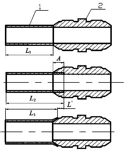
[0028] Step 1, specify the modeling method of flared catheter end for digital manufacturing, refer to figure 1 Carry out flaring conduit design modeling, the flare model of the conduit end is not established during modeling, so that the conduit end is flush with the end surface of the threaded joint;
[0029] Step 2, refer to figure 1 Define the flare compensation amount A of the conduit, and determine the flare compensation amount of conduits of different materials and specifications through finite element simulation and flare tests, and form a process parameter table as a process control amount for the manufacture of flared conduits.
[0030] Step three, refer to figure 1 , define the flare shrinkage of the conduit, and determine the flare shrinkage of conduits of different materials and specifications through experiments to form a process para...
Embodiment 2
[0046] The material is LF2, the outer diameter is 34mm, the wall thickness is 1mm, the length of the design modeling catheter is L1=450mm, and the catheter with single-end flare is taken as an example:
[0047] Step 1, refer to figure 1 Design modeling is carried out, and the design length of the conduit is L1=450.00mm.
[0048] Step 2, look up in the process parameter table, the material is LF2, the outer diameter is 34mm, and the wall thickness is 1mm, the catheter flaring compensation amount A=8.72mm, and the catheter flaring shrinkage amount L’=2.32mm.
[0049] Step three, refer to figure 1 , extract the design modeling conduit length L1, increase the conduit flaring compensation amount A at the end of the conduit, and obtain L2, that is, L2=L1+A=450.00mm+8.72mm=458.72mm.
[0050] Step 4, refer to figure 1 , carry out flaring processing on the catheter after increasing the flaring compensation amount, and obtain the length L3 of the catheter after flaring.
[0051] Ste...
Embodiment 3
[0054] The material is 1Cr18Ni9Ti, the outer diameter is 18mm, the wall thickness is 1mm, the design modeling conduit length L1=450mm, and the single-end flared conduit is an example:
[0055] Step 1, refer to figure 1 Design modeling is carried out, and the design length of the conduit is L1=450.00mm.
[0056] Step 2, look up in the process parameter table, the material is 1Cr18Ni9Ti, the outer diameter is 18mm, and the wall thickness is 1mm.
[0057] Step three, refer to figure 1 , extract the design modeling conduit length L1, increase the conduit flaring compensation amount A at the end of the conduit, and obtain L2, that is, L2=L1+A=450.00mm+4.98mm=454.98mm.
[0058] Step 4, refer to figure 1 , carry out flaring processing on the catheter after increasing the flaring compensation amount, and obtain the length L3 of the catheter after flaring.
[0059] Step 5, use the laser vector measuring machine to measure, and get the actual length L3=453.69mm after the catheter is...
PUM
 Abstract
Description
Claims
Application Information
 - R&D
- Intellectual Property
- Life Sciences
- Materials
- Tech Scout
- Unparalleled Data Quality
- Higher Quality Content
- 60% Fewer Hallucinations
Browse by: Latest US Patents, China's latest patents, Technical Efficacy Thesaurus, Application Domain, Technology Topic, Popular Technical Reports.
© 2025 PatSnap. All rights reserved.Legal|Privacy policy|Modern Slavery Act Transparency Statement|Sitemap|About US| Contact US: help@patsnap.com