
Antenna array

An antenna array and antenna unit technology, applied in the field of antenna arrays, can solve the problem that the antenna array cannot achieve broadband impedance bandwidth and other problems

Inactive Publication Date: 2018-12-21
LEIHUA ELECTRONICS TECH RES INST AVIATION IND OF CHINA
View PDF3 Cites 6 Cited by
  • Summary
  • Abstract
  • Description
  • Claims
  • Application Information

AI Technical Summary

Problems solved by technology

[0004] In order to solve the problems mentioned in the above-mentioned background technology, that is, in order to solve the problem that traditional antenna arrays cannot realize broadband impedance bandwidth

Method used

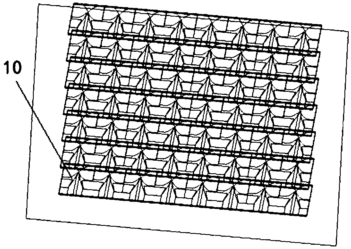
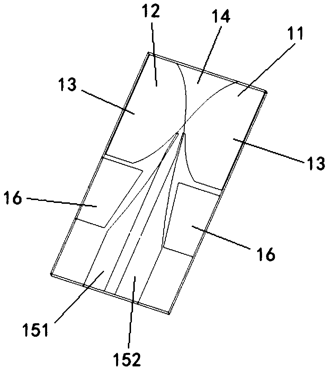
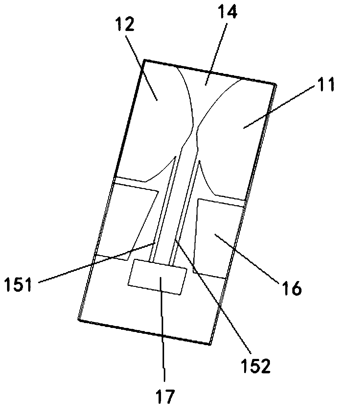

Image

  • Antenna array
  • Antenna array
  • Antenna array

Examples


Embodiment Construction

[0018] In order to make the objectives, technical solutions and advantages of the present invention clearer, the technical solutions in the embodiments of the present invention will be described in more detail below in conjunction with the drawings in the embodiments of the present invention. In the drawings, the same or similar reference numerals denote the same or similar elements or elements having the same or similar functions throughout. The described embodiments are some, but not all, embodiments of the invention. The embodiments described below by referring to the figures are exemplary and are intended to explain the present invention and should not be construed as limiting the present invention. Based on the embodiments of the present invention, all other embodiments obtained by persons of ordinary skill in the art without making creative efforts all belong to the protection scope of the present invention. Embodiments of the present invention will be described in deta...


PUM


Abstract

The invention belongs to the technical field of microwave antennas, and solves the problem that the broadband impedance bandwidth of the traditional antenna array cannot be realized. The invention provides an antenna array which comprises at least two antenna elements in the same row or column, and the distance between each two adjacent antenna elements is 5 to 50 mm, the antenna unit is used to widen the frequency band of the antenna array to 0.4 to 40GHz. The coupling introduced by the close arrangement of antenna elements can cancel out the low-frequency reactance introduced by the floor torealize the wideband antenna array operation, The invention can realize the wideband balun feed through the gradual change microstrip line, and can restrain the reflection of the metal floor to the electromagnetic wave of the specific frequency band through the resistance structure. At that same time, the invention also has the advantage of small volume, light weight, controllable cost, integrative printing processs and the like, and can be applied to various wideband antenna systems in large quantities. T

Description

technical field [0001] The invention belongs to the technical field of microwave antennas, and in particular relates to an antenna array. Background technique [0002] The traditional broadband phased array antenna design method first requires the design of an isolated antenna unit that meets the broadband requirements, and then organizes the broadband antenna array unit into an array, and through technical measures such as compensating or weakening the mutual coupling effect between the array elements, the Array elements also have broadband characteristics in the array environment. However, in the above-mentioned traditional broadband phased array antenna design method, it is difficult to overcome the contradiction between low-frequency coupling and high-frequency grating lobes, and because of the existence of the floor, harmful reactance will be introduced in a specific frequency band, making the antenna impedance unstable and impossible to achieve Broadband Impedance Ban...

Claims


Application Information

Patent Timeline
Patent Type & Authority Applications(China)
IPC IPC(8): H01Q1/36H01Q1/38H01Q1/50H01Q21/00
CPCH01Q1/36H01Q1/38H01Q1/50H01Q21/00
Inventor 郭星辰郑婷陈振中
Owner LEIHUA ELECTRONICS TECH RES INST AVIATION IND OF CHINA
Learn More