
A magnetic energy double-sided engine slip ring conductive composite copper wire

An engine and double-sided technology, applied in the direction of electromechanical devices, circuits, collectors, etc., can solve the problems of separation of composite copper wire and conductive slip ring, affecting the conductive effect of composite copper wire, etc., to reduce friction and reduce friction , wear reduction effect

Inactive Publication Date: 2018-12-21
汤亮
View PDF4 Cites 1 Cited by
  • Summary
  • Abstract
  • Description
  • Claims
  • Application Information

AI Technical Summary

Problems solved by technology

[0006] Aiming at the deficiencies in the prior art, the present invention provides a magnetic energy double-sided engine slip ring conductive composite copper wire, which solves the problem that when the magnetic energy double-sided engine slip ring conductive composite copper wire is in use, the conductive slip ring rotates due to the rotor, and the conductive slip ring The ring will squeeze the composite copper wire, so that there is a hidden danger of part of the composite copper wire being separated from the conductive slip ring, which will affect the conductive effect of the composite copper wire

Method used


Image

  • A magnetic energy double-sided engine slip ring conductive composite copper wire
  • A magnetic energy double-sided engine slip ring conductive composite copper wire
  • A magnetic energy double-sided engine slip ring conductive composite copper wire

Examples


Embodiment Construction

[0027] The following will clearly and completely describe the technical solutions in the embodiments of the present invention with reference to the accompanying drawings in the embodiments of the present invention. Obviously, the described embodiments are only some, not all, embodiments of the present invention. Based on the embodiments of the present invention, all other embodiments obtained by persons of ordinary skill in the art without making creative efforts belong to the protection scope of the present invention.

[0028] In describing the present invention, it is to be understood that the terms "opening", "upper", "lower", "thickness", "top", "middle", "length", "inner", "surrounding" etc. Indicating orientation or positional relationship is only for the convenience of describing the present invention and simplifying the description, and does not indicate or imply that the components or elements referred to must have a specific orientation, be constructed and operated in...


PUM


Abstract

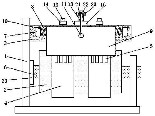
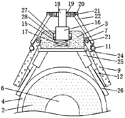
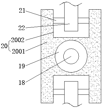
The invention discloses a magnetic energy double-sided engine slip ring conductive composite copper wire, which relates to the technical field of magnetic energy double-sided engine components. that the copper wire is provided with a fix rod, a pressing Plate, a threaded plug, a connection block and a connection rod, the fixing rod is rotated , causing the threaded plug to rotate and move downward, the fixing rod drives the connecting block to move downward through the rolling bearing, causing the connecting rod to move downward, the connecting rod pushes the pressing plate to rotate about thepin axis through the ball pin, the torsion spring returns to its normal condition, so that the platen presses the brush against the copper wire, the separation of the composite copper wire from the conductive slip ring under the extrusion of the conductive slip ring in the copper wire brush is avoided, the normal conductivity of the composite copper wire is not affected, As the rotor drives the conductive slip ring to rotate when the conductive composite cop wire of the slip ring of the magnetic energy double-sided engine is in use, the conductive slip ring will extrude the composite copper wire, so that the hidden trouble that a part of the composite copper wire and the conductive slip ring are separated, and the conductive effect of the composite copper wire is affected.

Description

technical field [0001] The invention relates to the technical field of magnetic energy double-sided engine components, in particular to a conductive composite copper wire for a magnetic energy double-sided engine slip ring. Background technique [0002] With the continuous development of science and technology, the demand for energy is increasing day by day. Natural resources such as carbon and oil can no longer meet the needs of society. It was discovered a long time ago that the two ends of magnets in nature have polarities, which have the characteristics of same-sex repulsion and opposite-sex attraction, and can form a magnetic field. Magnets are manufactured according to this phenomenon. With the modern advanced manufacturing technology of magnetism With the advancement of technology, a strong magnet with permanent magnetic force came into being. Combining two strong magnets within the combined magnetic field will continuously generate magnetic potential energy. Accordin...

Claims


Application Information

Patent Timeline
IPC IPC(8): H02K13/00H01R39/24H01R39/38
CPCH01R39/24H01R39/381H02K13/003
Inventor 汤亮
Owner 汤亮
Learn More