
A system and method for identify that initial position of a rotor of a permanent magnet synchronous motor

A technology of rotor initial position and permanent magnet synchronous motor, which is applied in the control system, generator control, motor control, etc. It can solve the problems of long time-consuming magnetic pole polarity discrimination, high current sampling accuracy, and the need to interrupt magnetic poles to achieve difficult magnetic poles. Misjudgment of polarity, fast identification speed and cost saving effect

Inactive Publication Date: 2018-12-21
JIANGSU UNIV
View PDF11 Cites 13 Cited by
  • Summary
  • Abstract
  • Description
  • Claims
  • Application Information

AI Technical Summary

Problems solved by technology

[0004] Purpose of the invention: The present invention solves the disadvantages of the existing permanent magnet synchronous motor rotor initial position magnetic pole polarity discrimination based on the high-frequency injection method, which takes a long time, has high sampling accuracy for the current, needs to interrupt the high-frequency signal injection process, and easily causes magnetic pole misjudgment, etc. , to provide a system and its identification method that can quickly and accurately identify the initial position of the rotor when the motor is stationary

Method used


Image

  • A system and method for identify that initial position of a rotor of a permanent magnet synchronous motor
  • A system and method for identify that initial position of a rotor of a permanent magnet synchronous motor
  • A system and method for identify that initial position of a rotor of a permanent magnet synchronous motor

Examples


Embodiment Construction

[0028] In order to make the above objects, features and advantages of the present invention more obvious and understandable, the specific implementation methods of the present invention will be described in detail below in conjunction with the accompanying drawings.

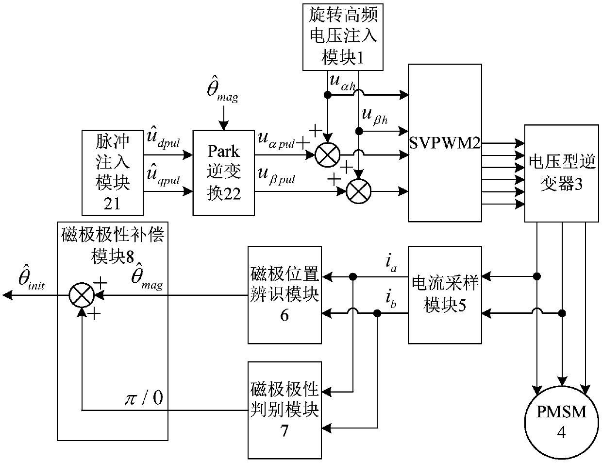
[0029] see figure 1 , a permanent magnet synchronous motor rotor initial position identification system of the present invention consists of a rotating high frequency voltage injection module 1, a SVPWM2 (i.e. a space vector pulse width modulation module 2), a pulse injection module 21, a Park inverse transformation module 22, a voltage type inverter It is composed of a device 3, a current sampling module 5, a magnetic pole position identification module 6, a magnetic pole polarity discrimination module 7 and a magnetic pole polarity compensation module 8.

[0030] Wherein, the output end of the pulse injection module 21 is connected to the input end of the Park inverse transformation module 22, and the output of...


PUM


Abstract

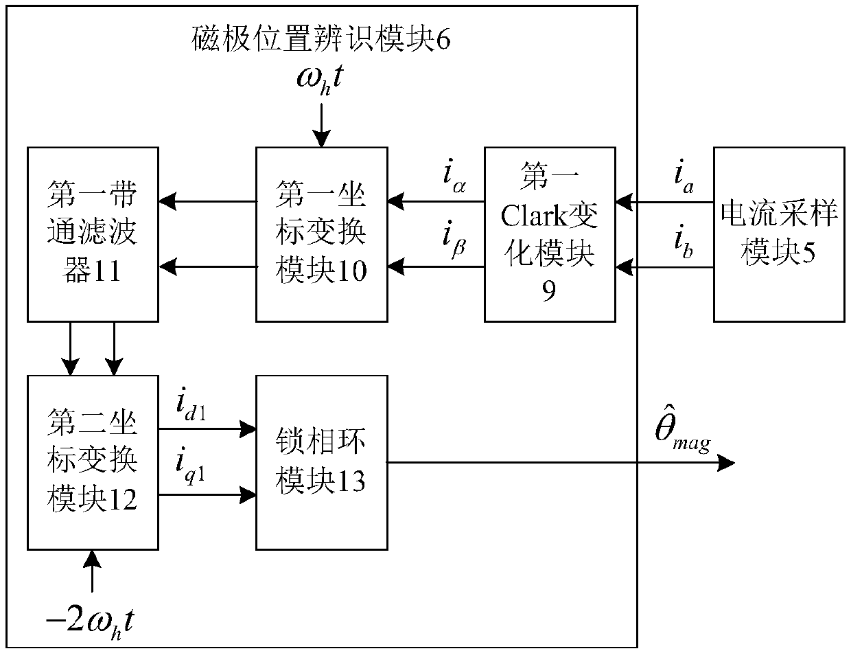
A system and method for identify that initial rotor position of permanent magnet synchronous motor in the field of motor is disclosed, the output of the pulse injection module is the pulse voltage component in the estimation coordinate system, the rotating high-frequency voltage injection module outputs the rotating high-frequency voltage in the stationary coordinate system, A magnetic pole position identification module and a magnetic pole polarity identification module are connected with each other at that output ends of the magnetic pole position identification module and the magnetic polepolarity identification module at the input end of the magnetic pole polarity compensation module. Only one pulse voltage signal needs to be injected, the polarity of magnetic pole can be distinguished by comparing the difference of inductance before and after pulse injection, Whether to compensate the position of the magnetic pole to obtain the initial position information of the rotor does not depend on the precision of the current sampling circuit. In the pulse injection process, the high-frequency injection signal need not be cut off, and the rotor can be directly started without positionafter the initial position of the rotor is accurately identified.

Description

technical field [0001] The invention belongs to the field of motor control, and in particular relates to an initial position identification technology of a permanent magnet synchronous motor rotor, which is suitable for starting occasions of a permanent magnet synchronous motor drive system without a position sensor. Background technique [0002] Permanent Magnet Synchronous Motor (PMSM) is widely used in emerging fields such as electric vehicles, industrial robots, and wind power generation due to its high power density, high efficiency, and low noise. In order to realize the high-precision and high-performance control of the PMSM drive system, it is necessary to accurately obtain the position information of the motor rotor. Regardless of whether a mechanical position sensor or a sensorless self-detection technology is used, it is necessary to accurately detect the initial position information of the rotor before starting the motor. If the error of the initial position of ...

Claims


Application Information

Patent Timeline
IPC IPC(8): H02P21/18H02P25/022
CPCH02P2203/03H02P2203/11H02P2207/05H02P21/18H02P25/024
Inventor 全力杜思宸朱孝勇张丽左月飞
Owner JIANGSU UNIV
Learn More