
Variable frequency step-down motor economizer

A technology for motors and power savers, which is applied in the direction of AC motor control, electrical components, and harmonic reduction devices. Low subharmonic components, continuous current waveform, and the effect of reducing terminal voltage

Inactive Publication Date: 2018-12-21
丁毅
View PDF0 Cites 0 Cited by
  • Summary
  • Abstract
  • Description
  • Claims
  • Application Information

AI Technical Summary

Problems solved by technology

The existing motor saver reduces the motor terminal voltage by controlling the conduction angle of the thyristor. The disadvantage of using the thyristor is that the waveform of the motor terminal voltage is discontinuous, the current waveform is discontinuous, and there are large high-order harmonics. Wave components, polluting the power grid

Method used


Image

  • Variable frequency step-down motor economizer
  • Variable frequency step-down motor economizer
  • Variable frequency step-down motor economizer

Examples


Embodiment 1

[0011] Embodiment 1 (applied to single-phase motor):

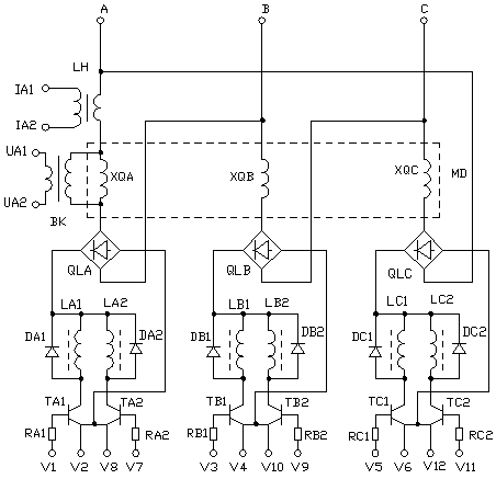
[0012] A frequency conversion step-down motor saver, which includes a main circuit and a frequency conversion control circuit, the main circuit includes an A-phase voltage regulation circuit, the A-phase voltage regulation circuit includes a full-wave rectifier QLA, the input terminal of the full-wave rectifier QLA is connected to the A-phase of the motor The phase windings are connected in series, the positive pole of the output terminal of the full-wave rectifier QLA is connected to the collector of the transistor TA1 through the inductor LA1, the emitter of the transistor TA1 is connected to the negative pole of the output terminal of the full-wave rectifier QLA, and the positive pole of the output terminal of the full-wave rectifier QLA is connected to the collector of the transistor TA2 through the inductor LA2 The electrode, the emitter of the triode TA2 is connected to the negative pole of the output end of the full-...

no. 2 example

[0023] Second embodiment (applied to three-phase motors in delta or star connection):

[0024] The delta connection method of the winding of the three-phase motor MD is as follows: figure 1 As shown, the first end of the A-phase winding XQA is connected to the A-phase power supply, the first end of the B-phase winding XQB is connected to the B-phase power supply, the first end of the C-phase winding XQC is connected to the C-phase power supply, and the tail end of the A-phase winding XQA is connected to the B-phase winding The head end of XQB, the tail end of the B-phase winding XQB is connected to the head end of the C-phase winding XQC, and the tail end of the C-phase winding XQC is connected to the head end of the A-phase winding XQA. One of the differences from the first embodiment is that the main circuit includes an A-phase voltage regulating circuit, a B-phase voltage regulating circuit, and a C-phase voltage regulating circuit. The A-phase voltage regulating circuit in...


PUM


Abstract

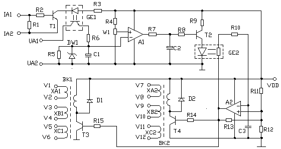
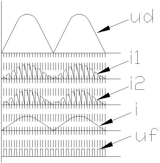
A variable frequency step-down motor economizer includes a voltage regulating circuit, and a variable frequency control circuit, A voltage regulating circuit comprises a full-wave rectifier, the inputof the full-wave rectifier is connected in series with the phase winding of the motor, A full-wave rectifier output terminal is connected with a pair of inductors and a series branch of a transistor,A frequency conversion control circuit includes a power factor detection circuit, a comparison circuit, a square wave oscillator, the frequency conversion control circuit controls the oscillation frequency of the square wave oscillator according to the power factor of the motor when it is running, When the triode is turned on alternately, the oscillation frequency and inductance reactance of themotor are increased when the motor is light load or no load, so that the terminal voltage of the motor is reduced and the power consumption is reduced. When the voltage is regulated, the triode is turned on alternately and the inductance is alternated with current, so that the voltage waveform of the motor terminal is continuous, the current waveform of the motor is continuous, and the high harmonic component is low, thereby avoiding the pollution to the electric network.

Description

technical field [0001] The invention relates to a motor saver. Background technique [0002] The power factor of the motor is low when it is no-load or light-loaded, and the method of reducing the terminal voltage of the motor is often used to improve the power factor and reduce power consumption. The existing motor saver reduces the motor terminal voltage by controlling the conduction angle of the thyristor. The disadvantage of using the thyristor is that the waveform of the motor terminal voltage is discontinuous, the current waveform is discontinuous, and there are large high-order harmonics. wave components, polluting the power grid. Contents of the invention [0003] Aiming at the deficiencies of the prior art, the present invention proposes a variable-frequency step-down motor saver, which, on the basis of ensuring power saving, makes the waveform of the motor terminal voltage continuous and reduces the pollution of high-order harmonics to the power grid. [0004] ...

Claims


Application Information

Patent Timeline
Patent Type & Authority Applications(China)
IPC IPC(8): H02P27/048H02P23/26H02J3/01
CPCH02J3/01H02P23/26H02P27/048Y02E40/40
Inventor 丁毅
Owner 丁毅
Learn More