Optical module

An optical module and optical path technology, applied in the field of optical modules, can solve the problems of increasing the difficulty of receiving high-speed burst signals for optical modules, and the technical difficulty of burst transimpedance amplifiers.

Inactive Publication Date: 2018-12-21
HISENSE BROADBAND MULTIMEDIA TECH
View PDF5 Cites 2 Cited by
  • Summary
  • Abstract
  • Description
  • Claims
  • Application Information

AI Technical Summary

Problems solved by technology

In the field of EPON, the optical module needs to be able to receive high-speed burst signals, but the technical difficulty of the burst transimpedance amplifier is relatively large, which increases the difficulty for the optical module to receive high-speed burst signals

Method used


Image

  • Optical module
  • Optical module
  • Optical module

Examples


Embodiment Construction

[0030] Reference will now be made in detail to the exemplary embodiments, examples of which are illustrated in the accompanying drawings. When the following description refers to the accompanying drawings, the same numerals in different drawings refer to the same or similar elements unless otherwise indicated. The implementations described in the following exemplary examples do not represent all implementations consistent with the present invention. Rather, they are merely examples of apparatuses and methods consistent with aspects of the invention as recited in the appended claims.

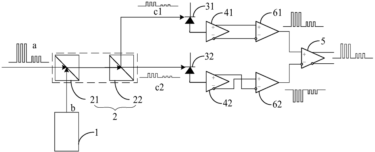
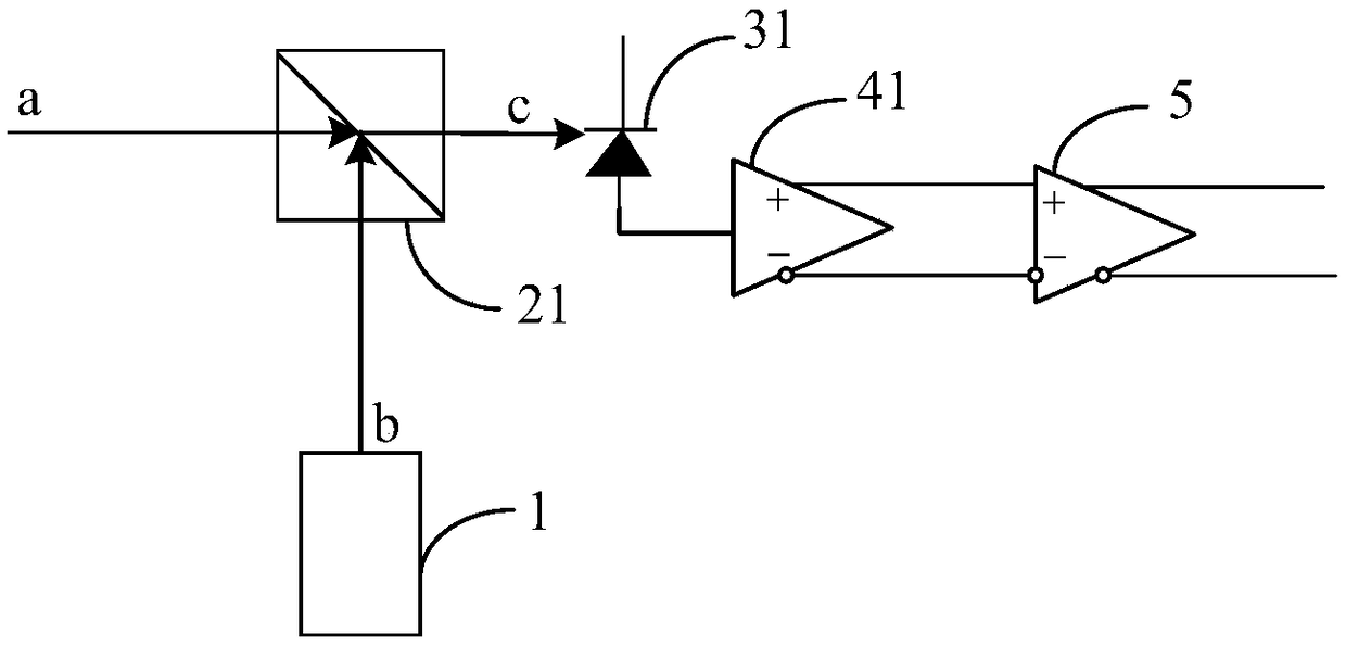
[0031] figure 1 An embodiment of the present invention, which is an optical module shown according to an exemplary embodiment, provides an optical module for receiving burst light a. Such as figure 1 As shown, the optical module includes: a light source device 1 , an optical coupling device 2 , a first photodetector 31 , a first transimpedance amplifier 41 , and a limiting amplifier 5 .

[00...


PUM


Abstract

The invention relates to an optical module, which relates to the technical field of optical fiber communication. The optical module is used for receiving burst light, and comprises a light source device, an optical coupling device, a first photodetector, a first transimpedance amplifier, and a limiting amplifier. The light source device is configured to emit continuous light having a wavelength identical to that of the burst light. The optical coupling device is used for receiving continuous light and burst light, and outputting a first optical signal obtained by combining the continuous lightand burst light, wherein the optical power difference of the first optical signal is smaller than the optical power difference of the burst light. The first photodetector is configured to receive thefirst optical signal and convert the first optical signal into a corresponding current signal. A first transimpedance amplifier is electrically connected to the first photodetector for converting a current signal into a first voltage signal in a continuous mode. The limiting amplifier is electrically connected to the first transimpedance amplifier for converting a digital signal corresponding tothe burst light based on the first voltage signal.

Description

technical field [0001] The invention relates to the technical field of optical fiber communication, in particular to an optical module. Background technique [0002] The optical module is an important part of the optical fiber communication system, which is used to receive optical signals and convert the optical signals into corresponding digital signals through signal conversion, signal amplification and other processes. Generally, an optical module includes a transimpedance amplifier for amplifying signals. [0003] With the development of communication technologies, 25G Ethernet Passive Optical Network (EPON) has become a mainstream trend of optical fiber communication systems. In the EPON field, the optical module needs to be able to receive high-speed burst signals, but the technical difficulty of the burst transimpedance amplifier is relatively large, which increases the difficulty for the optical module to receive high-speed burst signals. Contents of the invention...

Claims


Application Information

Patent Timeline
Patent Type & Authority Applications(China)
IPC IPC(8): H04B10/40H04B10/66
CPCH04B10/40H04B10/66
Inventor 张强赵其圣
Owner HISENSE BROADBAND MULTIMEDIA TECH
Why Eureka
Try Eureka