In-line hydraulic crimp tool

A technology for crimping tools and tools, applied in the field of hydraulic tools, can solve the problems of jaw casting defects, uneven cooling of metals, etc.

Active Publication Date: 2018-12-21
HUBBELL INC
View PDF8 Cites 2 Cited by
  • Summary
  • Abstract
  • Description
  • Claims
  • Application Information

AI Technical Summary

Problems solved by technology

In addition, the present inventors have realized that a disadvantage in the casting process of the amphoteric jaws

Method used


Image

  • In-line hydraulic crimp tool
  • In-line hydraulic crimp tool
  • In-line hydraulic crimp tool

Examples


Embodiment Construction

[0036] While the present invention will be shown and described in connection with a battery powered hand-held docking tool, those of ordinary skill in the art will readily appreciate that the inventive concepts and aspects of the present invention can be implemented in a variety of tools, fields and applications. The invention should not be considered limited to the embodiments described herein.

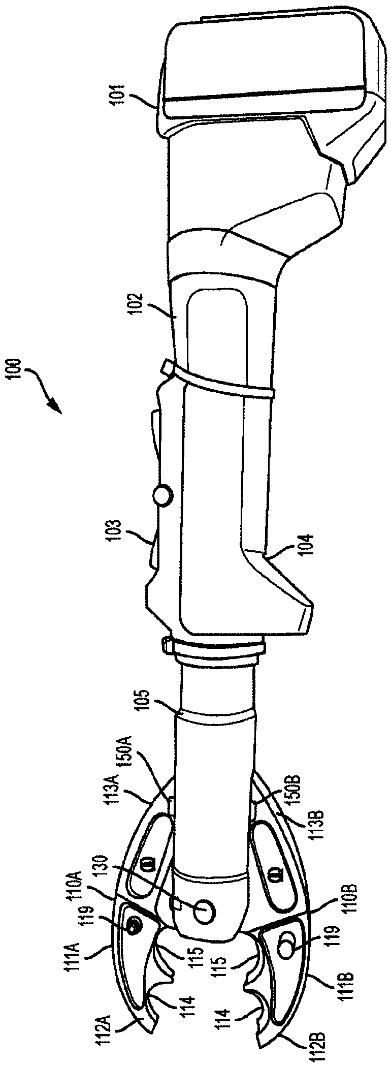
[0037] Such as figure 1 As shown, the battery powered crimping tool 100 includes a battery pack 101 , a handle portion 102 housing a control 103 and a handle 104 , a neck 105 and a pair of cooperating jaw members 110A, 110B.

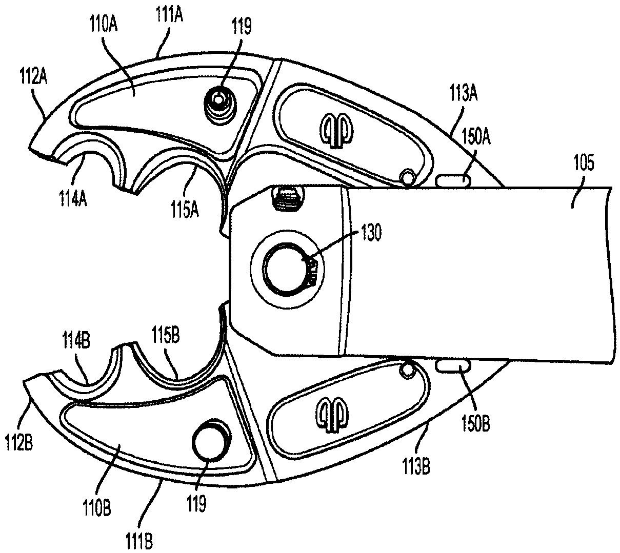
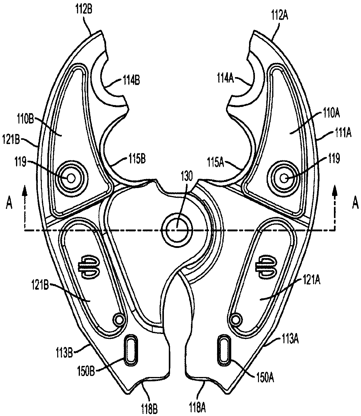
[0038] Such as figure 2 As best shown in 3 and 3, each jaw member includes a curved compression rod 111 having a front tip portion 112 and a rear portion 113. The inner region of the jaw rod defines one or more curved crimping surfaces 114 , 115 . In the illustrated embodiment, the jaws include crimping grooves 114,115. As understood by those of ordinary s...


PUM


Abstract

A crimp tool having jaw members joined in a tongue-in-groove connection held in place by a locking pin. Each jaw member is tapered and includes weight reducing pockets defined in respective sidewalls.Each jaw member includes a locking tab on an outside edge that mates with a respective locking tab opening in the neck of the tool. When the locking pin is removed, the jaws of the tool separate androtate away from one another until their respective locking tabs engage their respective locking tab opening, thereby holding the opened jaws in the neck of the tool.

Description

[0001] Cross References to Related Applications [0002] This application claims priority under 35 U.S.C. 119(e) to U.S. Provisional Application No. 62 / 330,598, filed May 2, 2016, the entire contents of which are incorporated herein by reference in their entirety. technical field [0003] The present invention relates to mating jaws and hydraulic tools having mating jaws. More specifically, the present invention relates to hydraulic hand-held crimping tools and jaw heads for crimping tools. Background technique [0004] Hand held hydraulic tools are well known in the art. These tools use mating jaws that are hydraulically pressed together with great force to crimp the material. These tools can be battery powered to allow user mobility and portability. These tools typically employ locking pins that hold the jaws together for the crimping operation. The locking pin is removed to remove the jaws. [0005] Typical features, controls and configurations of prior art crimping ...

Claims


Application Information

Patent Timeline
IPC IPC(8): B21D37/00B21D31/00B25B27/02B21J9/14B21J9/18H01R43/042B21F15/00B23D35/00B23D29/00B23D17/06F01B3/00
CPCB25B27/10H01R43/0427B25B28/00
Inventor 彼得·马修·沃森约翰·莱菲弗尔
Owner HUBBELL INC
Why Eureka
Try Eureka