Eureka AIR delivers breakthrough ideas for toughest innovation challenges, trusted by R&D personnel around the world.

Rotary belt conveyor for ship unloader

A belt conveyor, ship unloader technology, applied in the directions of loading/unloading, transportation and packaging, can solve the problems of easy extrusion, easy damage, damage, etc., to achieve convenient assembly and disassembly, prevent unnecessary damage, connection reliable results

Active Publication Date: 2018-12-25
台州万利电机泵业有限公司
View PDF4 Cites 0 Cited by
  • Summary
  • Abstract
  • Description
  • Claims
  • Application Information

AI Technical Summary

Problems solved by technology

[0002] Belt conveyor is the abbreviation of belt conveyor. It has fixed type and mobile type. It has simple structure and high efficiency. It is a continuous conveying machine with flexible conveyor belt as material carrying and traction components. An endless conveyor belt surrounds the driving drum and redirects Roller, the upper and lower branches between the two rollers are supported by a number of rollers, the material is placed on the upper branch, and the friction between the driving roller and the belt is used to drive the conveyor belt and the material to run. It is suitable for conveying bulk particles in horizontal and inclined directions. Materials and finished items can also be used in assembly lines for certain process operations. The structure is simple, the work is stable and reliable, the adaptability to materials is strong, the conveying capacity is large, the power consumption is small, and it is widely used. The belt conveyor is a rotating belt conveyor. Abbreviation, the belt conveyor uses the continuous or intermittent movement of the conveyor belt to transport various items of different weights. It can not only transport various bulk materials, but also transport various cartons, packaging bags and other light-weight items. It has a wide range of uses. , but it is easy to cause damage when unloading with the ship unloader, and it is easy to squeeze when the goods are placed, resulting in unnecessary damage

Method used

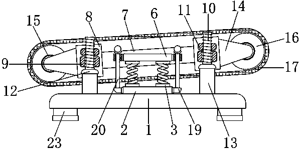

Image

  • Rotary belt conveyor for ship unloader
  • Rotary belt conveyor for ship unloader
  • Rotary belt conveyor for ship unloader

Examples


Embodiment Construction

[0014] The following will clearly and completely describe the technical solutions in the embodiments of the present invention with reference to the accompanying drawings in the embodiments of the present invention. Obviously, the described embodiments are only some, not all, embodiments of the present invention. Based on the embodiments of the present invention, all other embodiments obtained by persons of ordinary skill in the art without making creative efforts belong to the protection scope of the present invention.

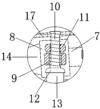
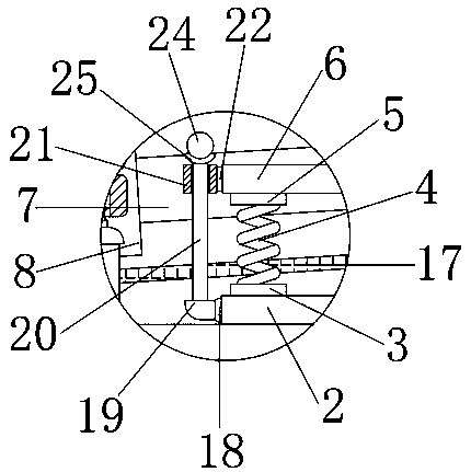
[0015] see Figure 1-3 , the present invention provides a technical solution: a rotary belt conveyor for a ship unloader, including a base plate 1, the base plate 1 is connected to the first connecting block 3 by an inner plate 2, and bases 23 are fixedly connected to the left and right sides of the bottom end of the base plate 1 , the base 23 is used to make the support of the base plate 1 more stable, the inner plate 2 is fixedly connected to the center of t...


PUM


Abstract

The invention discloses a rotary belt conveyor for a ship unloader, which comprises a base plate. The top center of the base plate is fixedly connected with an inner plate; the top of the spring is fixedly connected with a second connecting block, and the top of the second connecting block is fixedly connected with a head plate; the rear of the head plate is fixedly connected with a center rod, the left and right ends of the center rod are fixedly connected with a side block, and the front center of the side block is fixedly connected with a sleeve block. The top of the outer wall of the thread rod is connected with a thread bushing, and the bottom end of the thread rod is fixedly connected with a third connecting block. The outer wall of the rotary rod is connected with a round roller insleeve mode, the round roller is reservedly connected with the rotary rod, and the outer wall of the round roller is connected with a belt in sleeve mode. When the belt conveyor needs to be protected,the rotary belt conveyor for a ship unloader can improve the buffer protection through the matching of the center rod and the side block, thereby avoiding the extrusion of the conveyor when the goodsare placed, effectively protecting and reducing the damage, and preventing unnecessary damage.

Description

technical field [0001] The invention relates to the technical field of belt conveyors, in particular to a rotary belt conveyor for ship unloaders. Background technique [0002] Belt conveyor is the abbreviation of belt conveyor. It has fixed type and mobile type. It has simple structure and high efficiency. It is a continuous conveying machine with flexible conveyor belt as material carrying and traction components. An endless conveyor belt surrounds the driving drum and redirects Roller, the upper and lower branches between the two rollers are supported by a number of rollers, the material is placed on the upper branch, and the friction between the driving roller and the belt is used to drive the conveyor belt and the material to run. It is suitable for conveying bulk particles in horizontal and inclined directions. Materials and finished items can also be used in assembly lines for certain process operations. The structure is simple, the work is stable and reliable, the ad...

Claims


Application Information

Patent Timeline
IPC IPC(8): B65G67/60
CPCB65G67/60
Inventor 李鹤包秋菊吕宜鸿
Owner 台州万利电机泵业有限公司
Why Eureka
Eureka Blog
Learn More