Bench grinder for manufacturing polishing tool

A grinder and desktop technology, which is applied in the field of grinders, can solve the problems of desktop grinder heat generation, slow motor heat dissipation efficiency, and affect work efficiency, and achieve the effects of improving work efficiency, increasing single working hours, and simple structure

Inactive Publication Date: 2018-12-28
邬世文
View PDF1 Cites 1 Cited by
  • Summary
  • Abstract
  • Description
  • Claims
  • Application Information

AI Technical Summary

Problems solved by technology

However, there are still some problems in the use of desktop grinders on the market. For example, during the work process, the desktop grinder will generate vibration, which will affect the machining accuracy, and sparks will scatter during grinding, which may hit the operator. Or in the eyes, it will pose a certain threat to personal safety. When using the desktop grinder, people may make the desktop grinder work continuously for a long time, which will cause the desktop grinder to overheat and affect its service life.
[0003] In view of the above, the Chinese patent No. CN201721255513.2 proposed a desktop vibration-reducing grinder to a large extent to solve the above problems, but the solution to the excessive heating of the grinder is achieved by stopping its work , which limits the working hours of the grinder, and the heat dissipation efficiency of the motor inside the casing is slow, and it needs to stop working for a long time before putting it back into work, which greatly affects the working efficiency

Method used


Image

  • Bench grinder for manufacturing polishing tool
  • Bench grinder for manufacturing polishing tool
  • Bench grinder for manufacturing polishing tool

Examples


Embodiment Construction

[0019] The following will clearly and completely describe the technical solutions in the embodiments of the present invention with reference to the accompanying drawings in the embodiments of the present invention. Obviously, the described embodiments are only some, not all, embodiments of the present invention. Based on the embodiments of the present invention, all other embodiments obtained by persons of ordinary skill in the art without making creative efforts belong to the protection scope of the present invention.

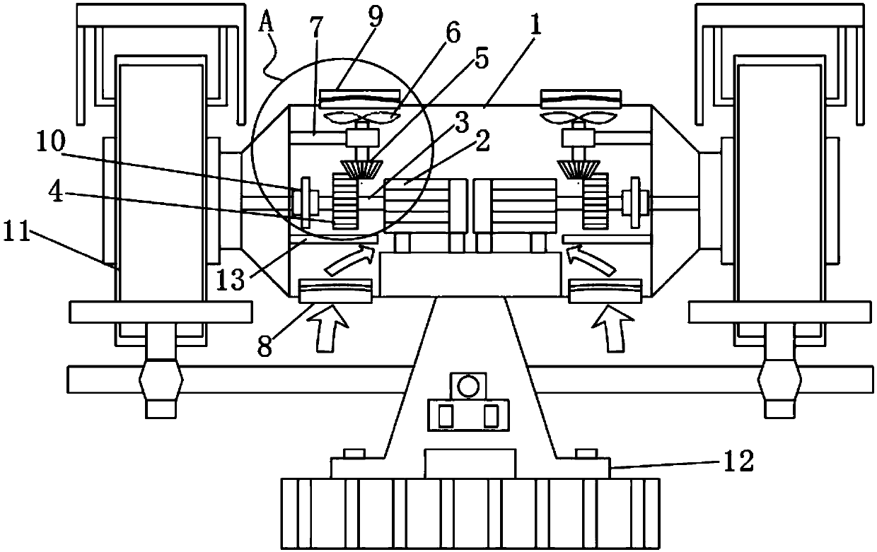
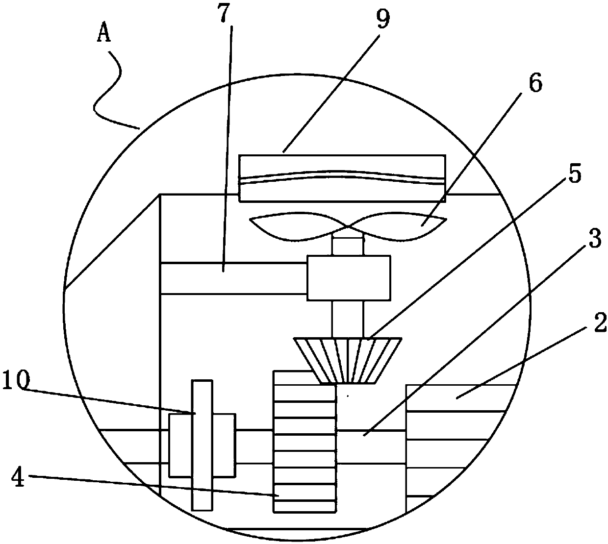
[0020] see Figure 1-3 , the present invention provides a technical solution: a desktop grinder for grinding tools, comprising a casing 1, a motor 2 is provided on both sides of the casing 1, and a transmission shaft 3 is provided on one side of the motor 2, and the transmission shaft 3 The upper cover is provided with a driving gear 4, and the top of the driving gear 4 is meshed with a bevel gear 5, the top of the bevel gear 5 is fixedly welded with a vertica...


PUM


Abstract

The invention discloses a bench grinder for manufacturing a polishing tool. The bench grinder comprises a housing. Two sides of the interior of the housing are provided with motors, and one side of the motor is provided with a transmission shaft. The transmission shaft is sheathed with a driving gear, and a bevel gear is meshed and installed above the driving gear. A vertical transmission rod is fixedly welded above the bevel gear, and an exhaust fan is fixedly welded above the vertical transmission rod. The vertical transmission rod is sheathed with a bearing, and one side of the bearing is fixedly welded with a support rod. One end of the support rod is fixedly welded with the inner wall in the housing, and two sides below the housing are provided with lower air inlets. An air drainage plate is fixedly installed above the lower air inlets. An air outlet is correspondingly installed above the exhaust fan. One end of the transmission shaft is connected with a coupling. The bench grinder is capable of performing heat-radiating treatment in a heating source, greatly increasing a one-time working time length of the grinder, and enabling working efficiency to be improved.

Description

technical field [0001] The invention relates to the technical field of grinding machines, in particular to a desktop grinding machine for grinding tools. Background technique [0002] The desktop grinder is a common equipment used to sharpen various knives and tools. In addition to some common requirements of grinding machine tools, the desktop grinder also has the characteristics of high speed, simple structure, wide application range, and generally manual operation. . However, there are still some problems in the use of desktop grinders on the market. For example, during the work process, the desktop grinder will generate vibration, which will affect the machining accuracy, and sparks will scatter during grinding, which may hit the operator. Or in the eyes, it will pose a certain threat to personal safety. When using the desktop grinder, people may make the desktop grinder work continuously for a long time, which will cause the desktop grinder to overheat and affect its s...

Claims


Application Information

Patent Timeline
Patent Type & Authority Applications(China)
IPC IPC(8): B24B3/00B24B55/02
CPCB24B3/00B24B55/02
Inventor 邬世文
Owner 邬世文
Why Eureka
Try Eureka