

Textile printing and dyeing wastewater treatment system
A wastewater treatment system, textile printing and dyeing technology, applied in textile industry wastewater treatment, water/sludge/sewage treatment, dehydration/drying/concentrated sludge treatment, etc., can solve the difficulty of cleaning the sludge in the lower hopper and increase the workload of workers and other problems to achieve the effect of avoiding blockage
Inactive Publication Date: 2018-12-28
张兴宇
View PDF8 Cites 1 Cited by
- Summary
- Abstract
- Description
- Claims
- Application Information
AI Technical Summary
Problems solved by technology
However, when the traditional textile printing and dyeing wastewater treatment system uses a sewage desilter to treat the wastewater, after the wastewater and the sludge are separated, the sludge is discharged and accumulated inside the holding container, and the accumulated sludge needs to be manually pushed evenly, which increases the The workload of the workers is increased, and the sludge located on the inner wall of the lower hopper is difficult to clean
Method used
View moreImage
Smart ImageViewing Examples

Examples
Embodiment Construction
Login to View More PUM
| Property | Measurement | Unit |
|---|---|---|
| angle | aaaaa | aaaaa |
Abstract
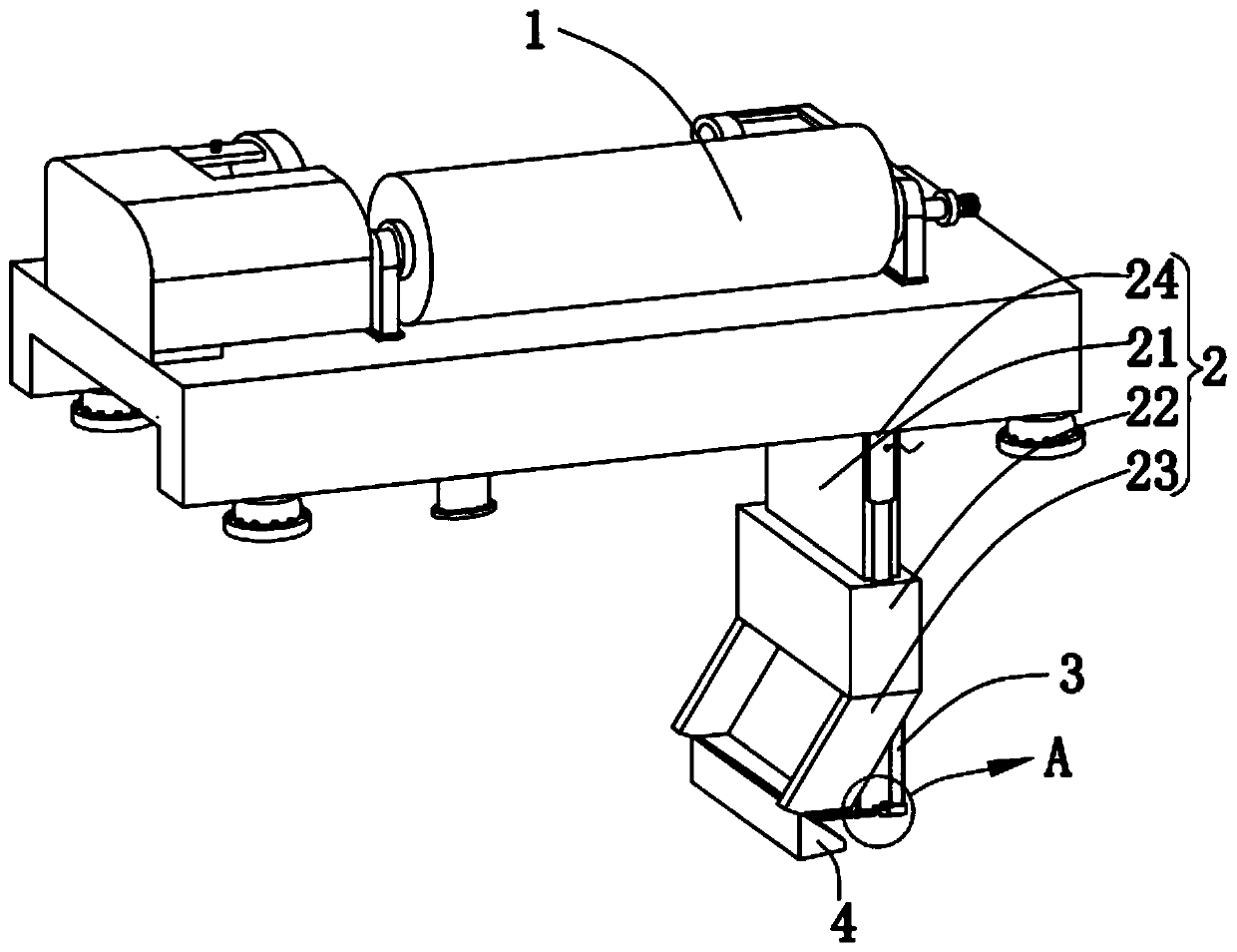
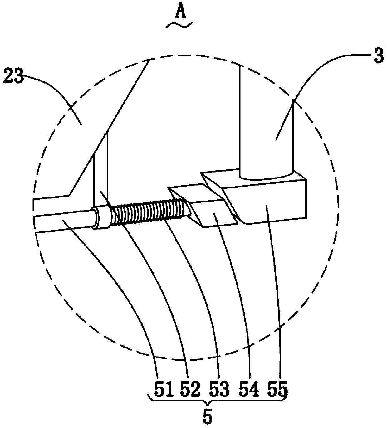
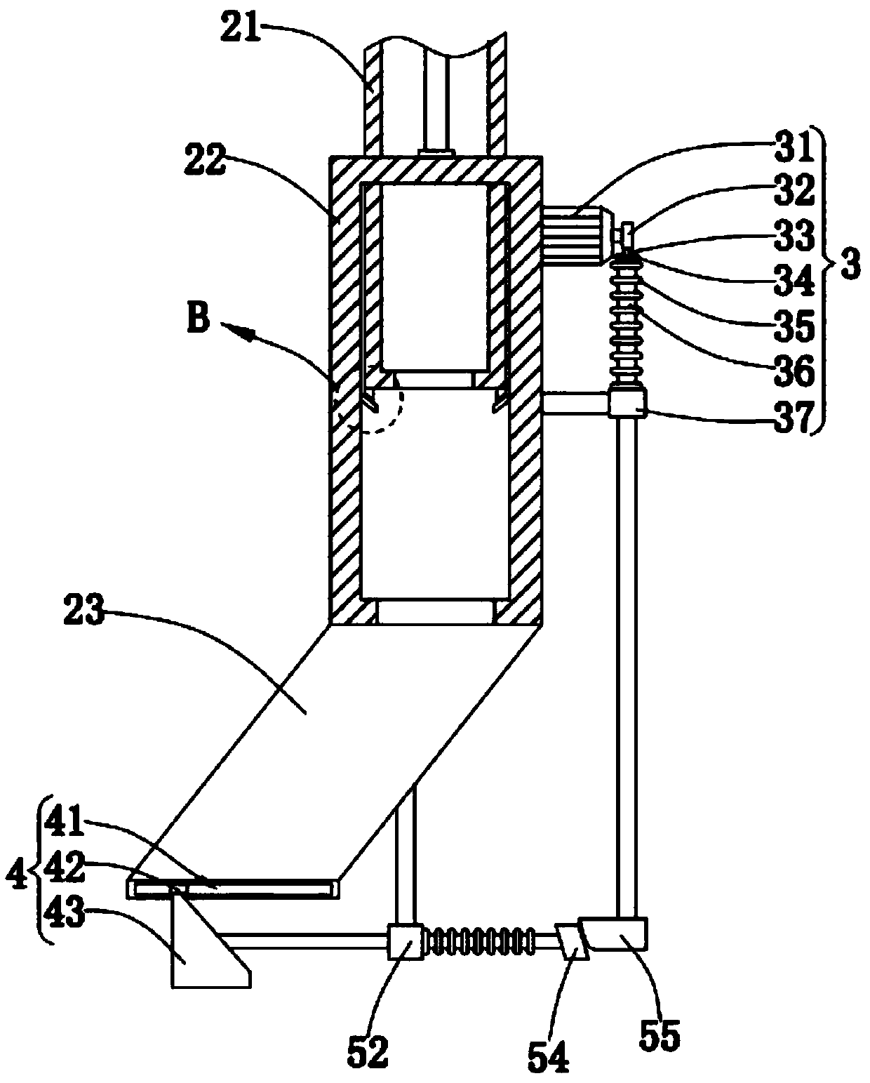
The invention relates to the field of textile printing and dyeing wastewater treatment, in particular to a textile printing and dyeing wastewater treatment system. The system comprises a sewage sludgeremoving machine, a discharging mechanism, a driving mechanism, a sludge pushing mechanism, a link mechanism and a sludge scraping mechanism, wherein the bottom of the sewage sludge removing machineis communicated with a discharging pipe used for discharging sludge; an electric drive pusher fixed with top of a connecting cylinder is mounted on the side wall of the discharging pipe; stretching and retraction of the electric drive pusher cooperate with placement of a sludge container, height of the electric drive pusher is adjusted according to the amount of sludge in the sludge container, anda drainage hopper is prevented from being blocked; the driving mechanism is mounted on the side wall of the connecting cylinder, a motor is powered on during beating of sludge, the link mechanism isbeaten by the driving mechanism, further, the sludge pushing mechanism is enabled to flatten sludge pushed and extruded together in the sludge container, and the defect of traditional manual pushing is overcome.
Description
technical field The invention relates to the field of textile printing and dyeing wastewater treatment, in particular to a textile printing and dyeing wastewater treatment system. Background technique Printing and dyeing is also called dyeing and finishing. It is a processing method, and it is also a general term for pretreatment, dyeing, printing, finishing, washing, etc.; the undergraduate dyeing and finishing major has now been incorporated into the light chemical engineering major, and the sludge dewatering machine is a continuous operation of sludge treatment. The equipment has a low moisture content in the mud, stable operation, low energy consumption, relatively simple control and management, and convenient maintenance. However, when the traditional textile printing and dyeing wastewater treatment system uses a sewage desilter to treat the wastewater, after the wastewater and the sludge are separated, the sludge is discharged and accumulated inside the holding conta...
Claims
Login to View More Application Information
Patent Timeline
 Patent Type & AuthorityApplications(China)
IPC IPC(8): C02F11/12C02F103/30
CPCC02F11/121C02F2103/30
Inventor张兴宇张家俊陈浩
Owner张兴宇