Eureka AIR delivers breakthrough ideas for toughest innovation challenges, trusted by R&D personnel around the world.

Plug-in electric rotary tiller

A rotary tiller and plug-in technology, which is applied in the field of plug-in electric rotary tillers, can solve problems such as difficulty in realizing stepless speed regulation, poor operation continuity, and complicated operation process, achieving less cost increase and high feasibility , good cohesion effect

Active Publication Date: 2019-01-01
安徽易疆科技有限公司
View PDF8 Cites 6 Cited by
  • Summary
  • Abstract
  • Description
  • Claims
  • Application Information

AI Technical Summary

Problems solved by technology

The rotary tillage machinery used in traditional agricultural production is driven by a diesel engine through a series of transmission devices and a standard mechanical PTO interface. This driving method makes it difficult for the rotary tiller to get rid of the influence of the engine speed, which means that The working speed of the rotary tiller is limited to several isolated speed points, and it is difficult to realize stepless speed regulation; in the traditional mechanical power transmission mode, in order to realize the soft combination of the blade of the rotary tiller when it enters the soil to reduce the impact on the blade and The impact of the engine is generally realized by controlling the slipping of the clutch, which not only wastes resources, but also has poor operation continuity and low operation efficiency; the power output interface of the traditional rotary tiller is a spline connection. The process is relatively complicated

Method used


Image

  • Plug-in electric rotary tiller
  • Plug-in electric rotary tiller
  • Plug-in electric rotary tiller

Examples


Embodiment Construction

[0045] The present invention will be described in further detail below in conjunction with the accompanying drawings.

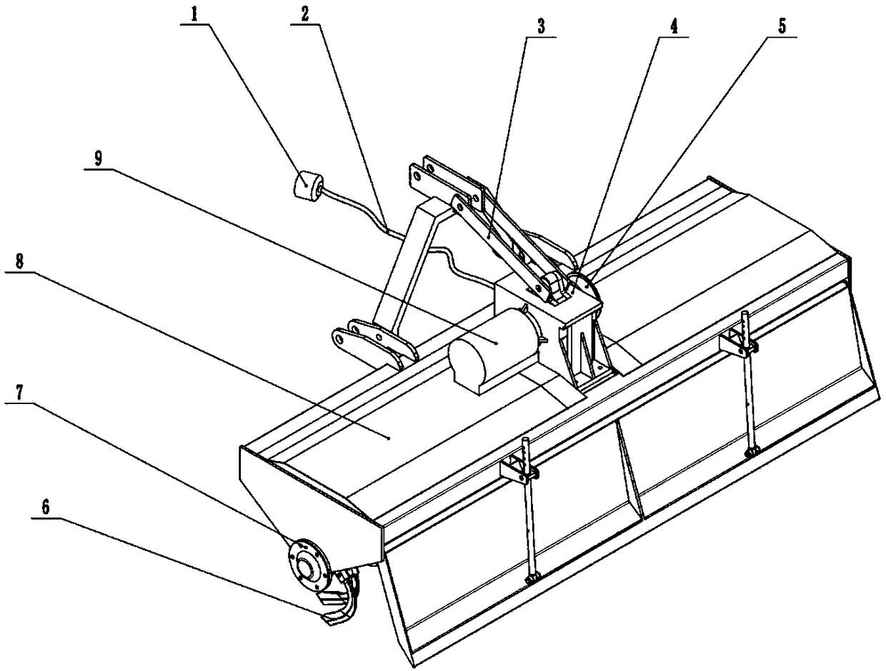
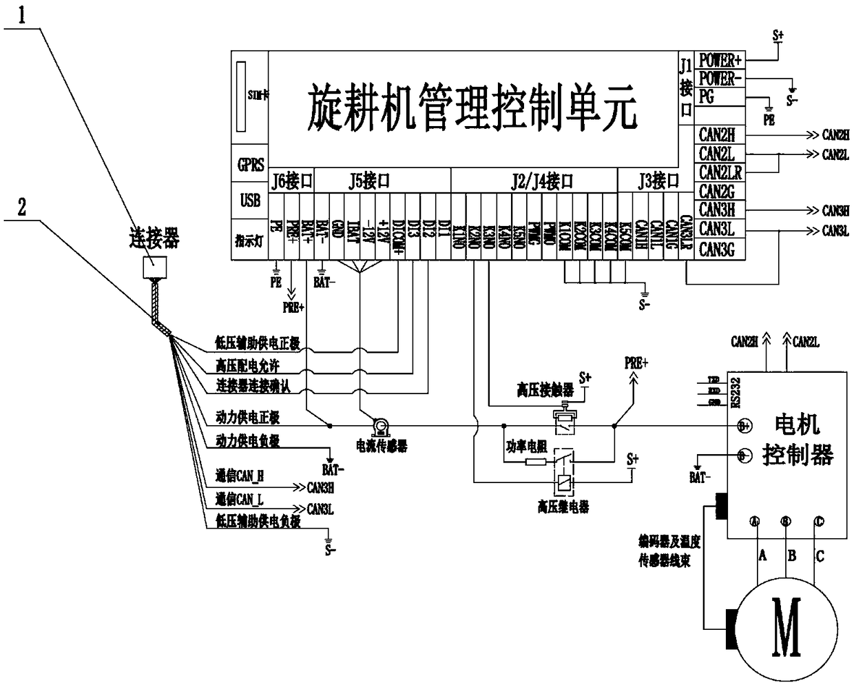
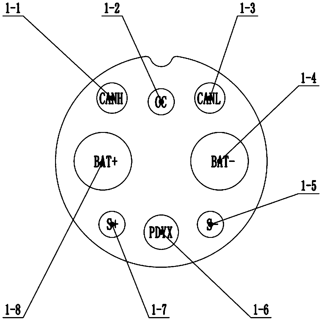
[0046] Based on the above analysis, the present invention discloses a plug-in electric rotary tiller, which combines figure 1 , its overall structure includes multi-contact electrical connector 1, power transmission cable 2, suspension rod 3, reducer assembly 4, electric control box 5, rotary cultivator roller cutter 6, roller cutter shaft assembly 7, rotary The cultivator body 8 and the motor drive device 9, the multi-contact electrical connector 1 can be respectively provided with one or more according to the voltage level and functional attributes; the multi-contact electrical connector 1 is connected to the power transmission One end of the cable 2; the power transmission cable 2 is a multi-core cable, and the number of effective cores of the power transmission cable 2 corresponds to the number of contacts of the multi-contact electrical connector 1; the ...


PUM


Abstract

The invention relates to a plug-in electric rotary tiller. The plug-in electric rotary tiller comprises a rotary tiller body, a rotary tiller roller cutter, a roller cutter shaft assembly, a suspension rod member, a reducer assembly, an electric control box body and a rotary tiller circuit assembly, wherein the rotary tiller circuit assembly includes an electrical interface part, an implement operation management part and an implement driving part, and the electrical interface part is used for quickly and reliably connecting the rotary tiller with an electric tractor by using a power transmission cable in a multi-contact electrical connector plugging mode, so that the rotary tiller circuit assembly is connected into the whole machine power grid of the electric tractor, and transmission ofelectric energy and data between the tractor and the rotary tiller is achieved; and the implement operation management part is used for performing coordinated management on power-on starting, implement driving, power-off stopping, high-voltage power safety management, implement running state monitoring, an electrical interface connection process and other processes of the rotary tiller, and the implement driving part is used for receiving demands of a rotary tiller management control unit, controlling a driving motor to output a corresponding electromagnetic torque, and driving the rotary tiller to work.

Description

technical field [0001] The invention relates to the field of tillage machinery, in particular to a plug-in electric rotary tiller. Background technique [0002] A rotary tiller is a tillage machine that is matched with a tractor to complete plowing and harrowing operations. The rotary tillage machinery used in traditional agricultural production is driven by a diesel engine through a series of transmission devices and a standard mechanical PTO interface. This driving method makes it difficult for the rotary tiller to get rid of the influence of the engine speed, which means that The working speed of the rotary tiller is limited to several isolated speed points, and it is difficult to realize stepless speed regulation; in the traditional mechanical power transmission mode, in order to realize the soft combination of the blade of the rotary tiller when it enters the soil to reduce the impact on the blade and The impact of the engine is generally realized by controlling the sl...

Claims


Application Information

Patent Timeline
Patent Type & Authority Applications(China)
IPC IPC(8): A01B33/02A01B33/08
CPCA01B33/021A01B33/082
Inventor 谢斌武仲斌宋正河于是张胜利李同辉温昌凯
Owner 安徽易疆科技有限公司
Why Eureka
Eureka Blog
Learn More