Supercharge Your Innovation With Domain-Expert AI Agents!

X-ray phase contrast imaging device

An imaging device and a phase difference technology are applied in measuring devices, radiological diagnostic equipment control, and radiodiagnostic instruments, etc., and can solve problems such as relative position offset, phase differential image and dark field image image quality degradation, etc.

Active Publication Date: 2022-03-15
SHIMADZU SEISAKUSHO CO LTD
View PDF7 Cites 0 Cited by
  • Summary
  • Abstract
  • Description
  • Claims
  • Application Information

AI Technical Summary

Problems solved by technology

[0006] However, in the X-ray phase difference imaging device disclosed in International Publication No. 2014 / 030115, the position of each grating is shifted in a plane perpendicular to the direction of the X-ray optical axis due to the grating holding part holding the grating during imaging. In the case of , the relative position of the self-image of the phase grating and the absorption grating shifts
In the case where the relative position of the self image of the phase grating and the absorption grating is shifted in the direction orthogonal to the direction in which the grating constituting portion of the grating extends, there is a problem that the shape of the acquired step curve changes , so the image quality of the generated phase differential image and dark field image deteriorates

Method used


Image

  • X-ray phase contrast imaging device
  • X-ray phase contrast imaging device
  • X-ray phase contrast imaging device

Examples


no. 1 approach

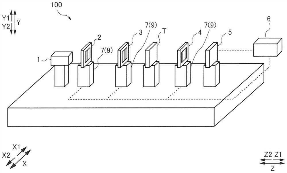
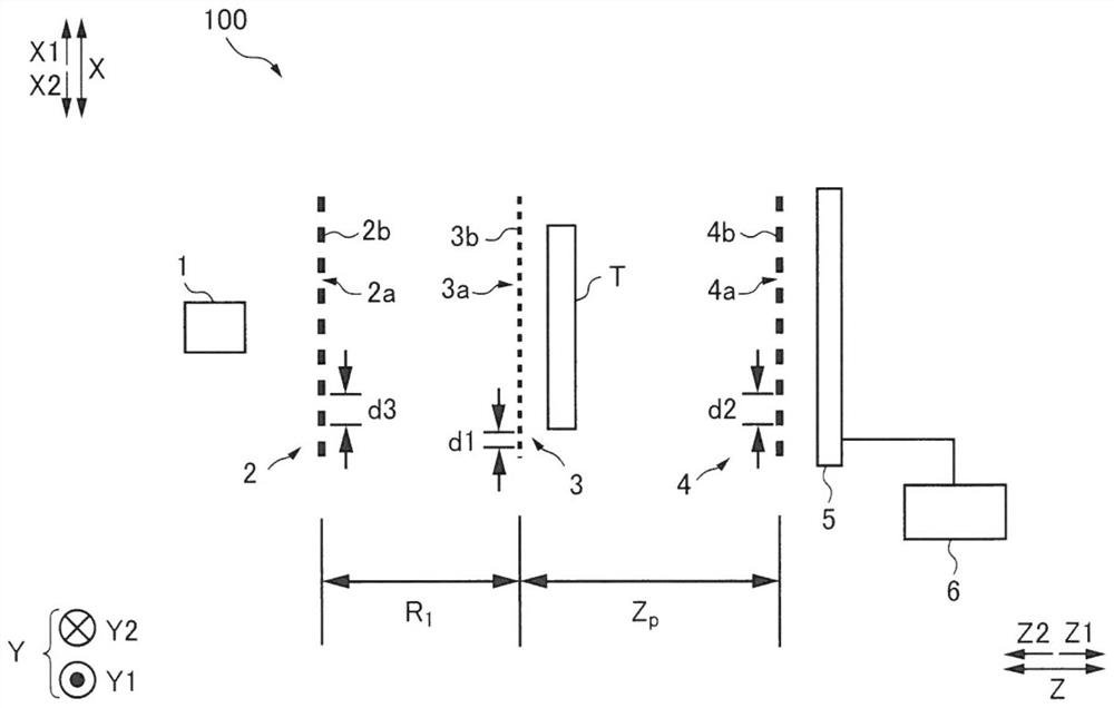
[0034] refer to Figure 1 to Figure 10 The configuration of the X-ray phase difference imaging device 100 according to the first embodiment of the present invention will be described.

[0035] (Structure of X-ray Phase Contrast Imaging Device)

[0036] First, refer to Figure 1 to Figure 6 The configuration of the X-ray phase contrast imaging apparatus 100 according to the first embodiment will be described.

[0037] Such as figure 1 As shown, the X-ray phase difference imaging device 100 is a device for imaging the inside of the subject T by utilizing the diffusion of X-rays passing through the subject T. In addition, the X-ray phase difference imaging device 100 is a device for imaging the inside of the subject T by utilizing the Talbot effect. The X-ray phase difference imaging device 100 can be used, for example, to image the inside of a subject T as an object in nondestructive inspection applications. In addition, the X-ray phase difference imaging device 100 can be ...

no. 2 approach

[0092] Next, refer to Figure 11 An X-ray phase difference imaging device 200 according to a second embodiment of the present invention will be described. The first grating 3 that includes changing the phase of X-rays irradiated from the X-ray source 1 to generate Talbot interference and the pair constitute an image generated due to the Talbot interference caused by the first grating 3 (self image 30 ) is different from the first embodiment of the second grating 4 that shields part of the X-rays irradiated from the X-ray source 1. The fourth grating 13 that shields a part of the X-rays of the generated image by shielding a part of the X-rays with the third grating 2 . In addition, the same code|symbol is attached|subjected to the same structure as said 1st Embodiment, and description is abbreviate|omitted.

[0093] Such as Figure 11 As shown, in the X-ray phase difference imaging device 200 of the second embodiment, the plurality of gratings include: the fourth grating 13,...


PUM

PropertyMeasurementUnit
thicknessaaaaaaaaaa

Abstract

The invention provides an X-ray phase difference imaging device. This X-ray phase difference imaging device includes a plurality of gratings and a grating holding unit for holding each of the plurality of gratings. The plurality of gratings are arranged such that a direction in which the grating constituent portions of the plurality of gratings extends in a plane perpendicular to the optical axis of the X-rays is along a direction in which a positional shift due to the grating holding portion is the largest.

Description

technical field [0001] The invention relates to an X-ray phase difference imaging device, in particular to an X-ray phase difference imaging device which uses a Talbot interferometer to generate absorption images, phase differential images and dark field images. Background technique [0002] Conventionally, there is known an X-ray phase difference imaging device that generates an absorption image, a phase differential image, and a dark field image using a Talbot interferometer. Such an X-ray phase difference imaging device is disclosed, for example, in International Publication No. 2014 / 030115. [0003] The X-ray phase difference imaging device disclosed in International Publication No. 2014 / 030115 includes an X-ray source, a multi-slit, a phase grating, an absorption grating, a detector, and a stepping device for moving the phase grating in steps. The X-ray phase difference imaging device disclosed in International Publication No. 2014 / 030115 moves a phase grating stepwise...

Claims


Application Information

Patent Timeline
Patent Type & Authority Patents(China)
IPC IPC(8): A61B6/00
CPCA61B6/5211A61B6/4035A61B6/4291G01N23/041A61B6/484A61B6/54G01N23/20008G01N23/20075
Inventor 堀场日明白井太郎土岐贵弘佐野哲森本直树
Owner SHIMADZU SEISAKUSHO CO LTD
Features
  • R&D
  • Intellectual Property
  • Life Sciences
  • Materials
  • Tech Scout
  • Unparalleled Data Quality
  • Higher Quality Content
  • 60% Fewer Hallucinations
Learn More