Environment-friendly dust removal device

A kind of dust removal equipment and environmental protection technology, applied in the field of environmental protection dust removal equipment, can solve the problems of single dust removal function and poor dust removal effect, achieve good dust removal effect, easy to clean, easy to clean and replace

Inactive Publication Date: 2019-01-01
郑旭鑫
View PDF0 Cites 2 Cited by
  • Summary
  • Abstract
  • Description
  • Claims
  • Application Information

AI Technical Summary

Problems solved by technology

[0004] Aiming at the deficiencies in the prior art, the present invention provides an environment-friendly dust removal equipment to solve the problems of poor dust removal effect and single dust removal function

Method used


Image

  • Environment-friendly dust removal device
  • Environment-friendly dust removal device
  • Environment-friendly dust removal device

Examples


Embodiment 1

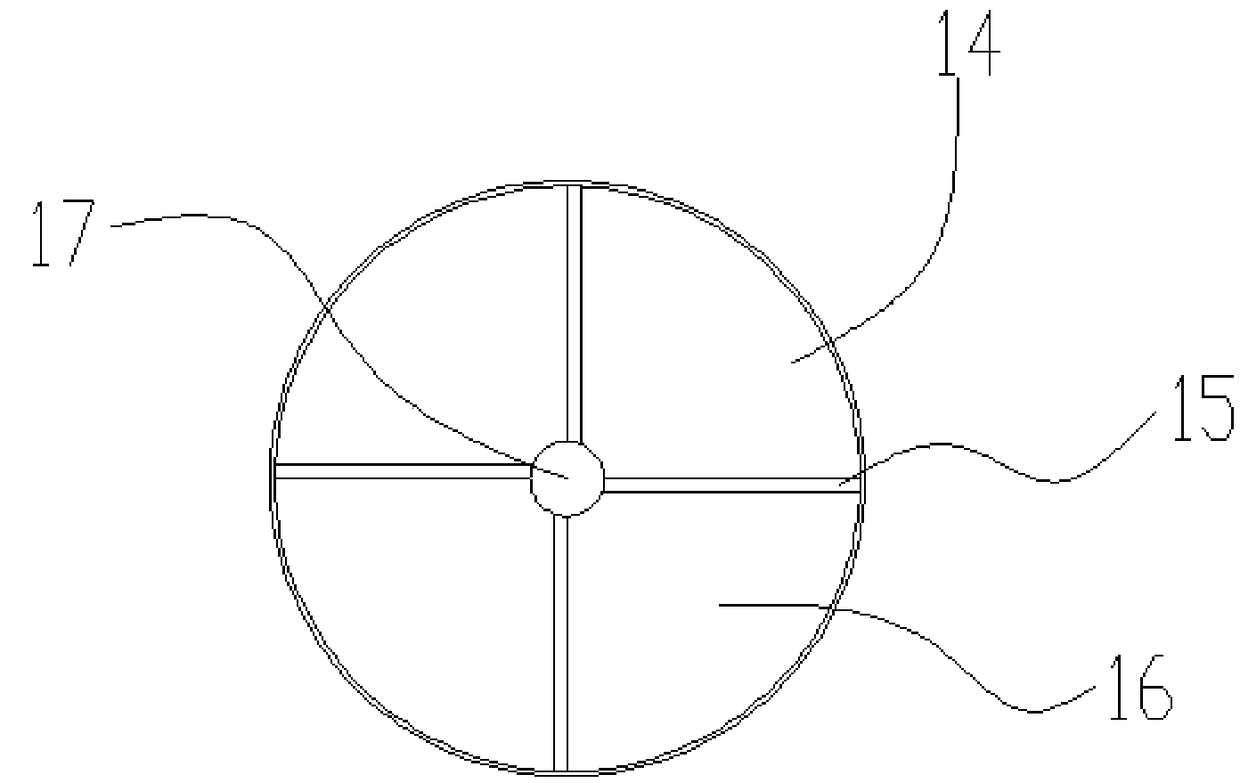
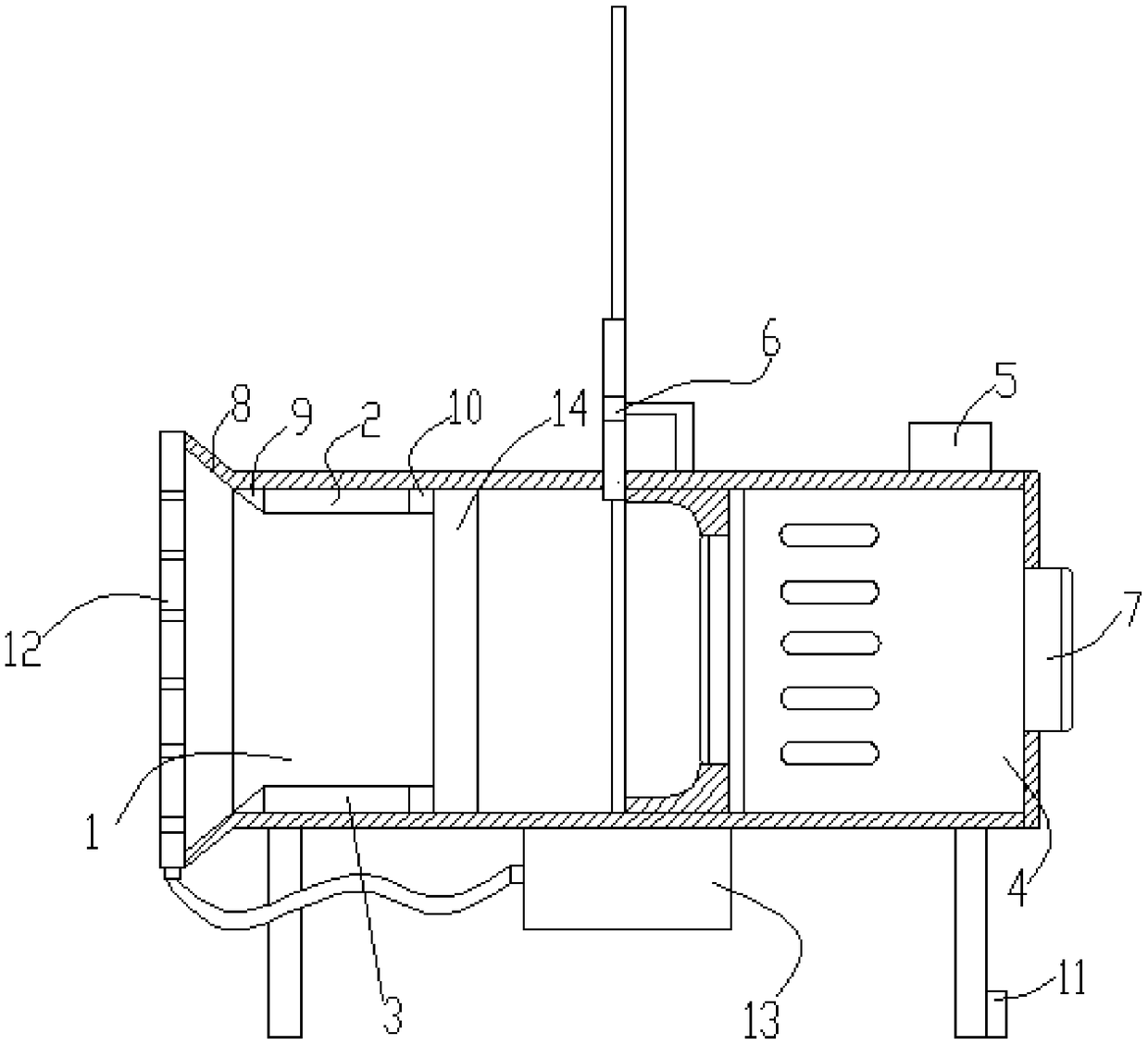
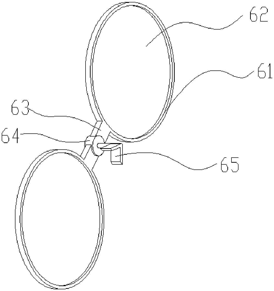
[0028] Such as Figure 1-3 As shown, it includes: dust removal part 1, first electrode plate 2, second electrode plate 3, fan 4, control device 5, filter device 6, exhaust port 7, pipe body 8, proximal insulation pad 9, remote insulation Pad 10, ground shrapnel 11, cooling device 12, water circulation device 13, blocking device 14, fixed rod 15, loose-leaf fan 16, fixed block 17, fixed ring 61, filter screen 62, rotating arm 63, rotating shaft 64 and fixed frame 65;

[0029] Such as figure 1 As shown, one end of the tube body 8 is provided with a dust removal part 1, and the dust removal part 1 is composed of a first electrode plate 2 and a second electrode plate 3; the first electrode plate 2 and the second electrode plate 3 are arranged on the inner wall of the tube body 8 The upper and lower sides are used to absorb the dust and particles in the gas passing through the dust removal part 1; the other end of the pipe body 8 is provided with a fan 4, and the tail end of the ...

Embodiment 2

[0037] Such as figure 2 As shown, compared with Embodiment 1, Embodiment 2 is provided with a blocking device 14 between the dust removal part 1 and the filter device 6 on the basis of Embodiment 1. The blocking device 14 includes: a fixed rod 15, a loose-leaf fan 16 and fixed block 17; fixed rod 15 and loose-leaf leaf 16 are set to four respectively, and one end of fixed rod 15 is fixed with the inwall of pipe body 8, and the other end is fixed with fast 17, and loose-leaf fan 16 is movably connected with fixed rod 15, and A torsion spring is provided at the joint, so that the loose-leaf fans 16 can swing in one direction. When there is no gas flow, the four loose-leaf fans 16 are closed. When the gas flows along the dust removal part 1 to the exhaust port 7, the loose-leaf fans 16 are opened; After the power is cut off, the loose-leaf fan 16 is automatically closed, and the dust adsorbed on the first electrode plate 2 and the second electrode plate 3 will not fall to the fi...


PUM


Abstract

The invention discloses an environment-friendly dust removal device. The environment-friendly dust removal device comprises a pipe body, a first electrode plate, a second electrode plate, a filter apparatus, a fan, a control apparatus and a cooling apparatus; one end of the pipe body is provided with a dust removal part, and the dust removal part consists of the first electrode plate and the second electrode plate; the first electrode plate and the second electrode plate are used for adsorbing the dust and micro-particles in the gas of the dust removal part; the other end of the pipe body is provided with the fan, the fan is provided with an exhaust opening, the fan is used for guiding the gas to pass through the dust removal part in the pipe body and discharging the gas from the exhaust opening; the filter apparatus is arranged in the pipe body and used for adsorbing the toxic and harmful substances of the gas; and the dust removal efficiency is effectively improved, by adopting the technical scheme, the requirement for the output power of the fan is relatively low, and the noise and electric power consumption in the working process of the dust removal device can be effectively reduced.

Description

technical field [0001] The invention relates to the field of air purification equipment, in particular to an environment-friendly dust removal equipment. Background technique [0002] At present, in the production and manufacturing of metallurgy, casting, cement building materials, machinery, light industry, and electric power, it is necessary to eliminate dust pollution, protect the environment, and improve working conditions. Different working conditions produce slightly different types of dust, so people have proposed different types of dust collectors. For example, in the polishing process, especially in the polishing of bamboo and wood products, there are characteristics of large dust particles and a large amount of dust; and in the rough grinding process of stainless steel and iron parts, a large number of dust particles with sparks are produced; Pretreatment is performed first, otherwise it will cause great harm to the human body; however, the existing dust removal e...

Claims


Application Information

Patent Timeline
IPC IPC(8): B03C3/014B03C3/155B03C3/47B01D53/02
CPCB03C3/014B01D53/02B01D2253/102B01D2257/93B01D2258/06B03C3/155B03C3/47
Inventor 胡正义
Owner 郑旭鑫
Why Eureka
Try Eureka