Full-servo numerical control pipe bending machine
A technology of pipe bending machine and servo motor, which is applied in the field of pipe bending processing, can solve the problems of low precision, low quality of pipe bending, and high labor intensity of replacement, so as to ensure consistency, ensure follow-up performance, and protect the surface of pipes Effect
- Summary
- Abstract
- Description
- Claims
- Application Information
AI Technical Summary
Problems solved by technology
Method used
Image
Examples
Embodiment 1
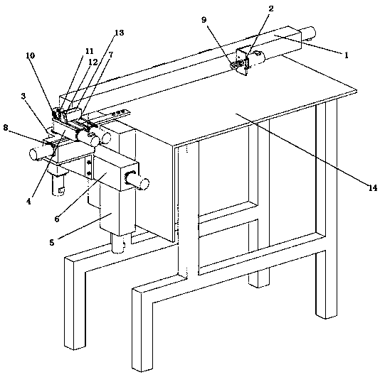
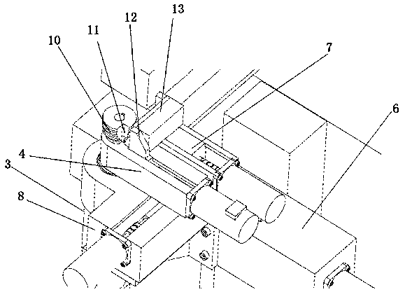
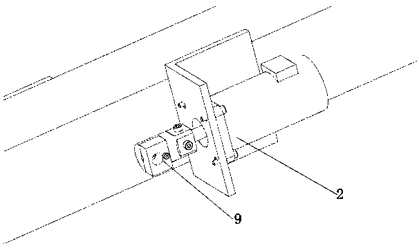
[0031] As a preferred embodiment of the present invention, with reference to the attached Figure 1-4 , this example discloses:
[0032] A full servo numerical control pipe bending machine, including a feeding mechanism 1, an angle rotation mechanism 2 and a pipe bending mechanism 3, the feeding mechanism 1 is used to transport pipe materials, and the angle rotation mechanism 2 is fixed on the feeding mechanism 1 Driven to move along the feeding direction; the angle rotation mechanism 2 is used to fix the pipe, and the pipe bending mechanism 3 is arranged at the output end of the feeding mechanism 1 for bending the pipe; it also includes a clamping mechanism 4 and a lifting mechanism 5 , horizontal moving mechanism 6, leaning plate mechanism 7 and follow-up mechanism 8, described clamping mechanism 4 is fixed on the bending pipe shaft of pipe bending mechanism 3, and rotates with the rotation of bending pipe shaft, the work of clamping mechanism 4 end is provided with a clamp...
Embodiment 2
[0035] As another preferred embodiment of the present invention, with reference to the attached Figure 1-4 , this example discloses:
[0036] A full servo numerical control pipe bending machine, including a feeding mechanism 1, an angle rotation mechanism 2 and a pipe bending mechanism 3, the feeding mechanism 1 is used to transport pipe materials, and the angle rotation mechanism 2 is fixed on the feeding mechanism 1 Driven to move along the feeding direction; the angle rotation mechanism 2 is used to fix the pipe, and the pipe bending mechanism 3 is arranged at the output end of the feeding mechanism 1 for bending the pipe; it also includes a clamping mechanism 4 and a lifting mechanism 5 , horizontal moving mechanism 6, leaning plate mechanism 7 and follow-up mechanism 8, described clamping mechanism 4 is fixed on the bending pipe shaft of pipe bending mechanism 3, and rotates with the rotation of bending pipe shaft, the work of clamping mechanism 4 end is provided with a...
Embodiment 3
[0048] As another preferred embodiment of the present invention, with reference to the attached Figure 1-4 , the concrete bending process of the present invention is:
[0049] (1) Install one end of the welding head of the pipe to be bent in the cavity of the pipe chuck 9, and place the other end of the welding head of the pipe to be bent in the groove of the pipe bending mold 10 and between the clamping shaft.
[0050] (2) The lifting shaft moves up and down, and the horizontal moving shaft moves left and right so that the pipe bending die 10 is at a specified radius position.
[0051] (3) The clamping shaft and the support plate move axially to the pipe bending die 10 to clamp the pipe. The pipe bending shaft, follower shaft and feeding shaft move simultaneously to complete the pipe bending action.
[0052] (4) The bending shaft drives the clamping shaft to rotate 180°, the follower shaft drives the plate shaft to follow the linear motion (moving distance is the arc lengt...
PUM
 Abstract
Description
Claims
Application Information
 - R&D
- Intellectual Property
- Life Sciences
- Materials
- Tech Scout
- Unparalleled Data Quality
- Higher Quality Content
- 60% Fewer Hallucinations
Browse by: Latest US Patents, China's latest patents, Technical Efficacy Thesaurus, Application Domain, Technology Topic, Popular Technical Reports.
© 2025 PatSnap. All rights reserved.Legal|Privacy policy|Modern Slavery Act Transparency Statement|Sitemap|About US| Contact US: help@patsnap.com


