
Feeding device of laser pipe cutter

A technology of feeding device and pipe cutting machine, which is applied in laser welding equipment, welding equipment, metal processing and other directions, can solve the problems of low processing efficiency, heavy weight, work injury, etc., and achieve high work efficiency, convenient operation and simple structure. Effect

Pending Publication Date: 2019-01-01
TIANJIN RENYIHE AUTOMATION TECH
View PDF0 Cites 2 Cited by
  • Summary
  • Abstract
  • Description
  • Claims
  • Application Information

AI Technical Summary

Problems solved by technology

However, for steel pipes with larger diameters, their weight is also greater. If manual feeding is still used, it will undoubtedly increase the workload of workers, and accidents will occur if they are not careful, and the processing efficiency is low.

Method used


Image

  • Feeding device of laser pipe cutter
  • Feeding device of laser pipe cutter
  • Feeding device of laser pipe cutter

Examples


Embodiment Construction

[0028] It should be noted that, in the case of no conflict, the embodiments of the present invention and the features in the embodiments can be combined with each other.

[0029] In describing the present invention, it should be understood that the terms "center", "longitudinal", "transverse", "upper", "lower", "front", "rear", "left", "right", The orientations or positional relationships indicated by "vertical", "horizontal", "top", "bottom", "inner", "outer", etc. are based on the orientation or positional relationships shown in the drawings, and are only for the convenience of describing the present invention Creation and simplification of description, rather than indicating or implying that the device or element referred to must have a specific orientation, be constructed and operate in a specific orientation, and therefore should not be construed as limiting the invention. In addition, the terms "first", "second", etc. are used for descriptive purposes only, and should no...


PUM


Abstract

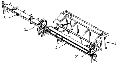
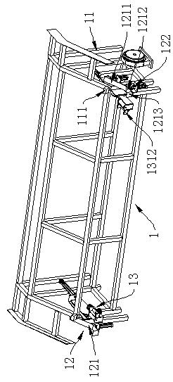
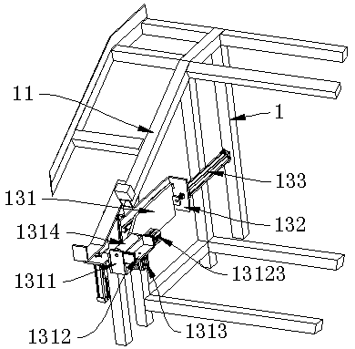
The invention provides a feeding device of a laser pipe cutter. The feeding device comprises a feeding frame, a first base and a second base, wherein the feeding frame is positioned at one side of thefirst base, and the second base is positioned at one end of the first base. The feeding mechanism comprises a sliding plate, a first support and a pushing cylinder, wherein the sliding plate is in sliding connection with the first support, and one end of the sliding plate is fixedly connected with a telescopic rod of the pushing cylinder. The sliding plate is provided with a second support, the second support is provided with a clamping jaw and an upward moving cylinder, and the clamping jaw is slidably connected with the second support and is fixedly connected with a telescopic rod of the upward moving cylinder. According to the feeding device of the laser pipe cutter, the sliding plate is driven by the pushing cylinder to realize the horizontal movement of a steel pipe, and the clampingjaw is then driven by the upward moving cylinder to realize the up-and-down movement, so that the steel pipe automatic feeding is realized, the structure is simple, and the working efficiency is high.

Description

technical field [0001] The invention belongs to the field of steel pipe cutting equipment, and in particular relates to a feeding device for a laser pipe cutting machine. Background technique [0002] Traditional laser cutting machines use manual loading. When a steel pipe is cut, it needs to be manually pushed to load the steel pipe. However, for steel pipes with larger diameters, the weight is also relatively large. If manual feeding is still used, the labor load of workers will undoubtedly be increased, and work-related injuries will occur if there is a slight carelessness, and the processing efficiency is low. Contents of the invention [0003] In view of this, the present invention aims to propose a feeding device for a laser pipe cutting machine to realize automatic material distribution and loading of steel pipes, reduce the labor load of workers, and improve processing efficiency. [0004] In order to achieve the above object, the technical solution created by the...

Claims


Application Information

Patent Timeline
Patent Type & Authority Applications(China)
IPC IPC(8): B23K26/70B23K26/38B23Q7/04
CPCB23K26/702B23K26/38B23Q7/04
Inventor 安志诚
Owner TIANJIN RENYIHE AUTOMATION TECH
Learn More