
Chemical vapor deposition during additive manufacturing

An object, fusion technology, used in machining, tooling, additive manufacturing, etc., to solve problems of poor quality, inability of customers and manufacturers to distinguish originals from replicas, etc.

Active Publication Date: 2019-01-01
GENERAL ELECTRIC CO
View PDF20 Cites 6 Cited by
  • Summary
  • Abstract
  • Description
  • Claims
  • Application Information

AI Technical Summary

Problems solved by technology

As a result, cheap replicas of items can flood the market, and such replicas can be of inferior quality compared to the original brand name product
However, after a single visual inspection of an intact item, neither the customer nor the manufacturer may be able to distinguish the original from the replica

Method used


Image

  • Chemical vapor deposition during additive manufacturing
  • Chemical vapor deposition during additive manufacturing
  • Chemical vapor deposition during additive manufacturing

Examples


Embodiment Construction

[0054] The detailed description set forth below in connection with the accompanying drawings is intended as a description of various configurations and is not intended to represent the only configurations in which the concepts described herein may be practiced. The detailed description includes specific details that provide a thorough understanding of various concepts. It will be apparent, however, to one skilled in the art that these concepts may be practiced without these specific details. In some instances, well-known components are shown in block diagram form in order not to obscure concepts.

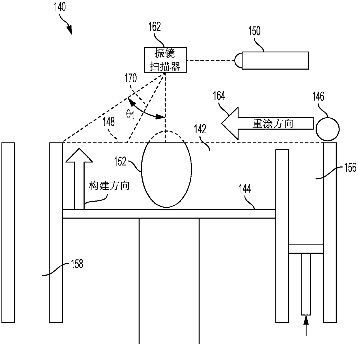
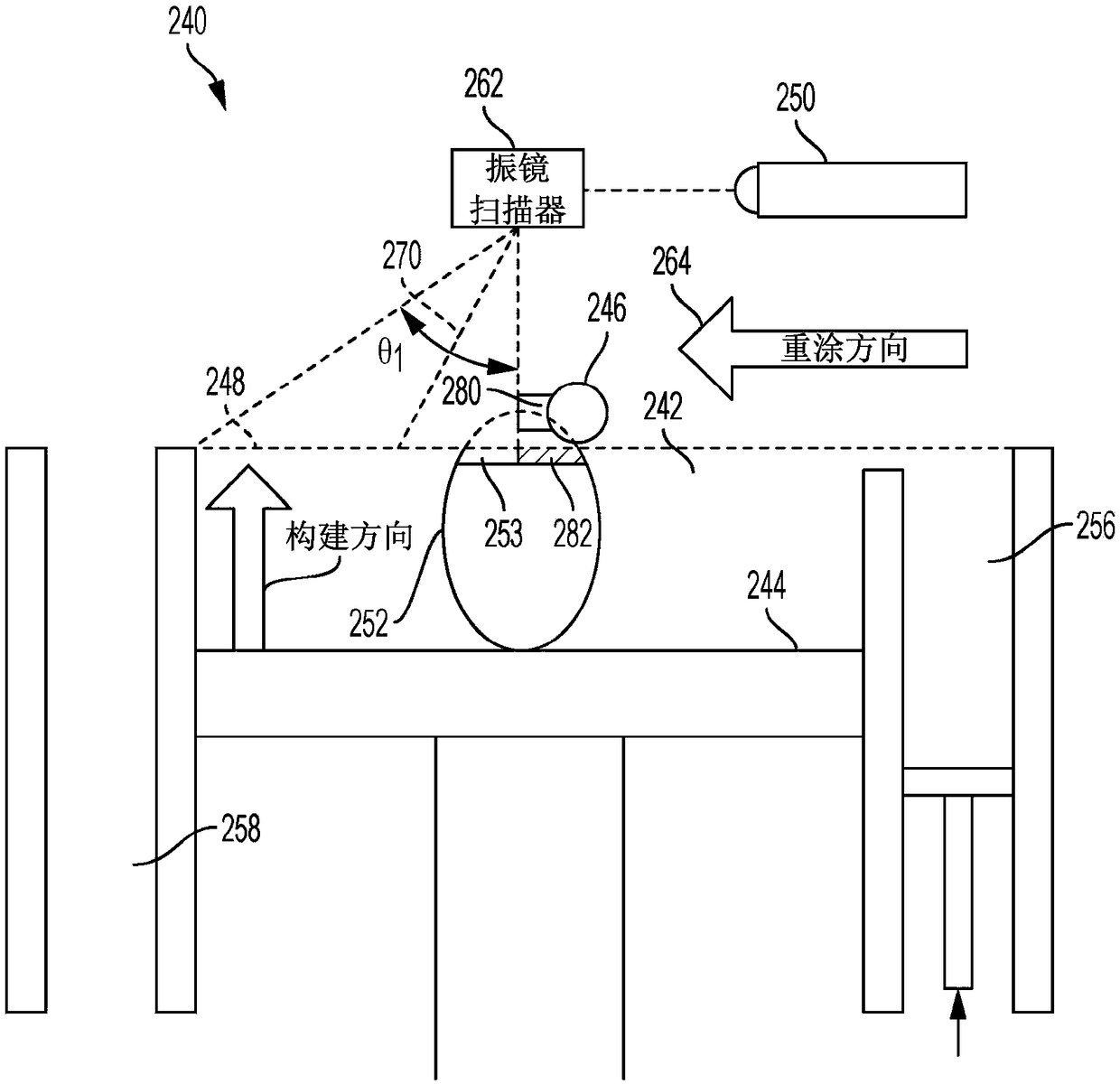
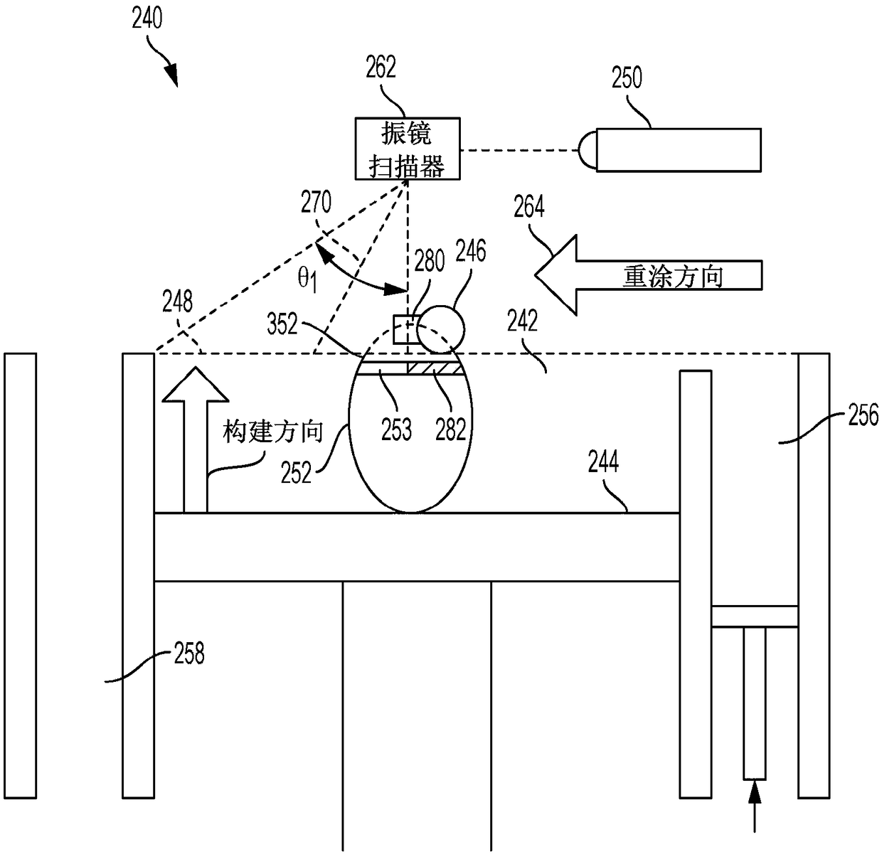
[0055] The present application relates to methods and apparatus for chemical vapor deposition (CVD) during additive manufacturing (AM) processes. CVD can be used during the AM process to add chemical tags during manufacturing, thus facilitating the process of distinguishing original products from replicas, which may be of lower quality.

[0056] According to the present disclosure...


PUM

PropertyMeasurementUnit
thicknessaaaaaaaaaa

Abstract

The present disclosure generally relates to methods and apparatuses for chemical vapor deposition (CVD) during additive manufacturing (AM) processes. Such methods and apparatuses can be used to embedchemical signatures into manufactured objects, and such embedded chemical signatures may find use in anti-counterfeiting operations and in manufacture of objects with multiple materials.

Description

technical field [0001] The present disclosure generally relates to methods and apparatus for chemical vapor deposition (CVD) during additive manufacturing (AM) processes. Background technique [0002] In contrast to subtractive manufacturing methods, additive manufacturing (AM) or additive printing processes typically involve the accumulation of one or more materials to form a net-like or near-net-like (NNS) object. Although "additive manufacturing" is an industry standard term (ASTMF2792), AM encompasses a variety of manufacturing and prototyping techniques known under a variety of names, including freeform manufacturing, 3D printing, rapid prototyping / machining, and more. AM technology enables the fabrication of complex parts from a wide range of materials. In general, individual objects can be manufactured from computer-aided design (CAD) models. Certain types of AM processes use electromagnetic radiation, such as a laser beam, to melt or sinter powder materials to form...

Claims


Application Information

Patent Timeline
Patent Type & Authority Applications(China)
IPC IPC(8): B29C64/153B29C64/20B28B1/00B22F3/105B22F3/24B22F3/22B33Y30/00B33Y10/00
CPCB33Y10/00B33Y30/00B29C64/153B29C64/20B22F3/225B22F3/24B28B1/001B22F2003/242B22F10/00B22F10/36B22F10/62B22F12/49B22F10/28B22F12/224B22F12/70B22F12/67B22F10/50B22F10/14B22F10/64B33Y40/00B33Y40/20B29C64/165C23C16/50C23C16/04B22F2999/00B22F7/02B22F7/06Y02P10/25C23C16/00B22F7/04C23C16/52B23K15/0086B23K26/342B23K26/082
Inventor S.A.戈德
Owner GENERAL ELECTRIC CO
Learn More