
Multifunctional vehicle-mounted tool box and use method thereof

A vehicle-mounted toolbox and multi-functional technology, which is applied in the direction of storing tools, vehicle parts, and special positions of the vehicle, can solve the problems of manual pulling out of the toolbox, easy tripping of the driver, and low degree of automation, so as to eliminate potential safety hazards , high degree of automation, smooth movement effect

Active Publication Date: 2019-01-01
江苏亚楠电子科技有限公司
View PDF4 Cites 0 Cited by
  • Summary
  • Abstract
  • Description
  • Claims
  • Application Information

AI Technical Summary

Problems solved by technology

The handle of the toolbox is exposed on the outside, which is easy to trip the driver; the toolbox needs to be pulled out manually, the degree of automation is low, and the safety is relatively poor; in addition, the toolbox is at a low position, and the driver needs to bend down to take out the tool when using it. More importantly, it is only a toolbox without maximizing its functions

Method used


Image

  • Multifunctional vehicle-mounted tool box and use method thereof
  • Multifunctional vehicle-mounted tool box and use method thereof
  • Multifunctional vehicle-mounted tool box and use method thereof

Examples


Embodiment 1

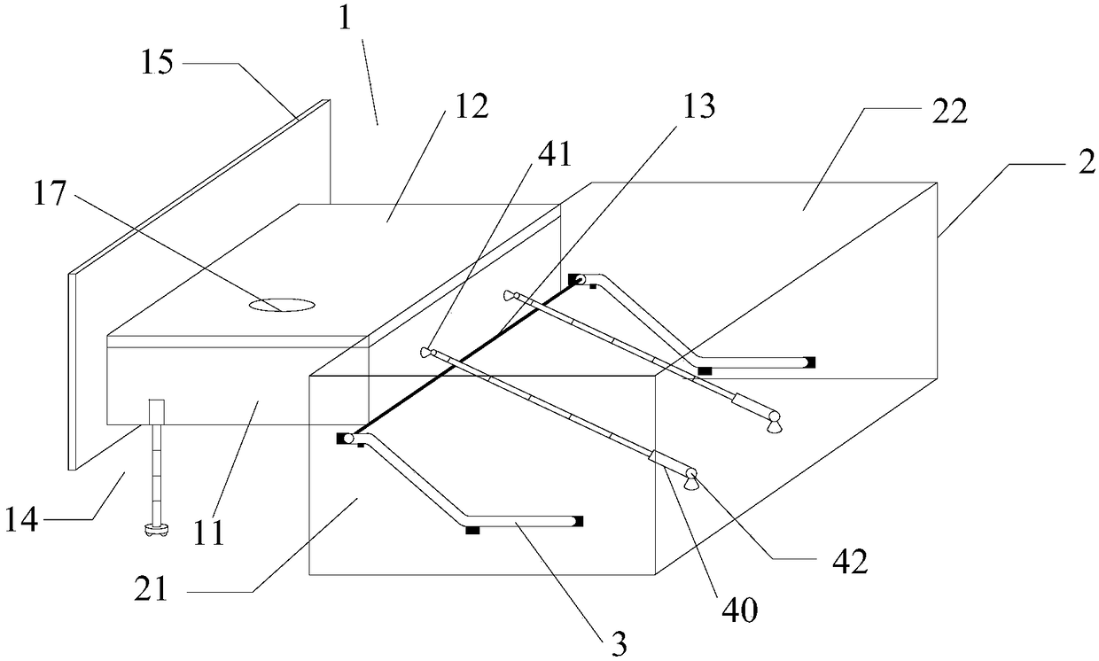
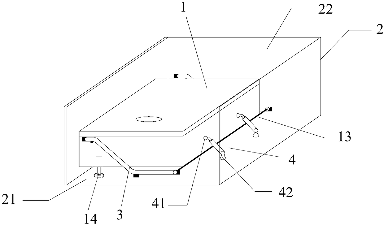
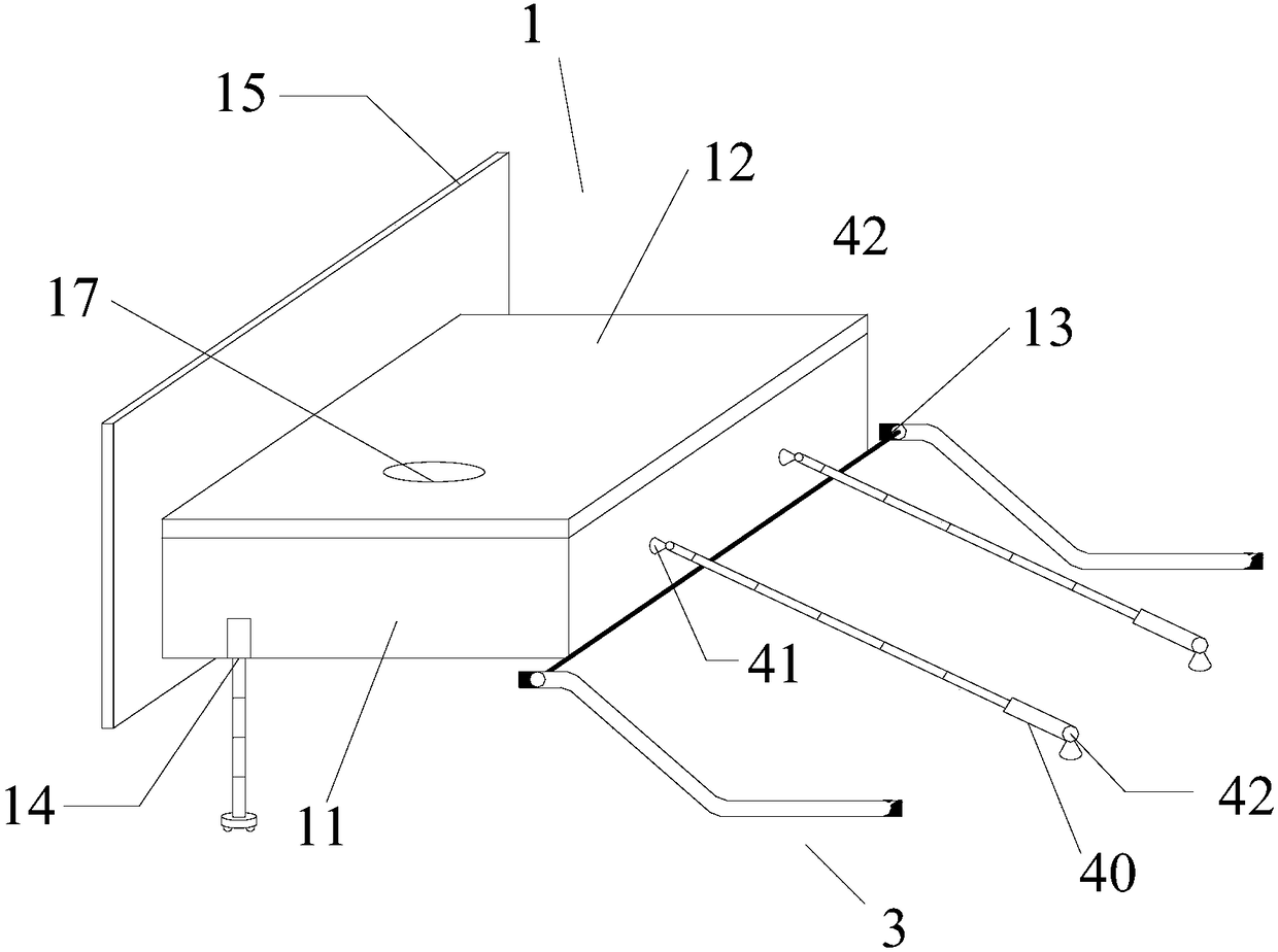
[0060] Such as figure 1 Shown in -5, a kind of multifunctional vehicle-mounted tool box, described tool box 1 is arranged between car seat 2 and car floor; Comprising:

[0061] A box body 11, the rear side of the box body 11 is provided with a pulley assembly 13; the front side wall is provided with a sealing plate 15;

[0062] Slide rail assembly 3, described slide rail assembly 3 is provided with two groups, is symmetrically fixedly arranged on the inner wall of left and right car seat supports 21; The inclined portion 33 provided on the front side of the car seat 2 is tilted upward, and the inclined portion 33 transitions smoothly with the horizontal portion; by setting the inclined portion 33 on the guide rail, the box body 11 can be automatically raised when it is stretched out, and the driving Operators can easily access tools without bending over.

[0063] Described pulley assembly 13 is slidably matched with slide rail assembly 3 so that box body 11 can stretch out o...

Embodiment 2

[0077] A method of using the aforementioned multifunctional vehicle toolbox, including extending and retracting the hidden method,

[0078] The extending method includes the following steps:

[0079] (1) Click the "toolbox open button" on the touch screen or press the "toolbox open button" on the car or remote control, and send out the electric control signal;

[0080] (2) The extending electric control signal is transmitted to the vehicle controller, and the vehicle controller controls the second electric telescopic rod 40 to start extending;

[0081] (3) The second electric telescopic rod 40 slowly stretches out and pushes the box body 11, the box body 11 drives the support shaft 132, and the pulleys 131 at both ends of the support shaft 132 slide along the second horizontal part 32 to make the box body 11 Translate to the front side of the car seat 2;

[0082] (4) When the pulley 131 rolls to the position of the fourth in-position sensor 37, the fourth in-position sensor ...


PUM


Abstract

The invention discloses a multifunctional vehicle-mounted tool box arranged between that automobile seat and the automobile floor, the tool box includes a box body provided with a pulley assembly, a slide rail assembly slidably engaged with the pulley assembly, a telescopic support assembly and an auto-telescopic drive assembly, the slide rail assembly includes a horizontal portion and a tilt portion tilted upward along a rear side of the vehicle seat toward a front side of the vehicle seat, the pulley assembly slidably cooperating with the slide rail assembly to enable the cabinet to protrudeor retract from the bottom of the vehicle seat; the telescopic support assembly is installed at the bottom of the front side of the box body for supporting the box body so as to keep the box body ina horizontal state. The invention also discloses a use method of a multifunctional vehicle-mounted tool box, which comprises an extension method and a retraction concealment method. The invention hasthe advantages of high automation degree, good safety and strong function.

Description

technical field [0001] The invention relates to the field of vehicle equipment, in particular to a multifunctional vehicle toolbox and a method for using the same. Background technique [0002] Car toolbox, as the name suggests, is a container for storing tools and various sundries in the car. With the popularity of cars, it has been widely used. [0003] Most of the existing vehicle toolboxes are directly placed in the trunk or in the car. The car is prone to collisions during driving, resulting in scratches on the car, damage to the box, and tool damage, which affects normal use and also poses a greater safety hazard. [0004] In view of the above technical problems, Chinese patent (CN201610341058.1) discloses a toolbox arranged between the car seat body and the car floor. The toolbox includes: a box body; There is an entrance and exit on the top, and the box body enters and exits the box cover along the first direction through the entrance and exit; the outer wall of the...

Claims


Application Information

Patent Timeline
Patent Type & Authority Applications(China)
IPC IPC(8): B60R7/04B60R11/06B60N3/00B60R16/033
CPCB60N3/008B60R7/043B60R11/06B60R16/033
Inventor 陈恺
Owner 江苏亚楠电子科技有限公司
Learn More