A rare earth alloy material melting system

A technology of rare earth alloy and discharge port, which is applied in the field of rare earth alloy material smelting system, can solve the problems of low automatic control ability and low crushing efficiency, and achieve the effect of improving the degree of mechanization and automation, high crushing efficiency and improving efficiency

Active Publication Date: 2020-01-14
丹阳市佳恒特种合金材料有限公司
View PDF6 Cites 0 Cited by
  • Summary
  • Abstract
  • Description
  • Claims
  • Application Information

AI Technical Summary

Problems solved by technology

[0004] In the above patent document 1, the smelting and multiple crushing of the rare earth alloy material are realized by setting the left and right chambers, the left and right crushing rods, the melting chamber, and the cooling plate, so as to improve the material properties of the rare earth alloy material, but the rare earth alloy material is crushed and smelted. When the device crushes the rare earth alloy material, it can only stir and crush the rare earth alloy material in one plane, but cannot press the rare earth alloy material in the vertical direction, so that part of the rare earth alloy material is stirred up during crushing, and the crushing efficiency is low; at the same time, the device low automatic control

Method used


Image

  • A rare earth alloy material melting system
  • A rare earth alloy material melting system

Examples


Embodiment Construction

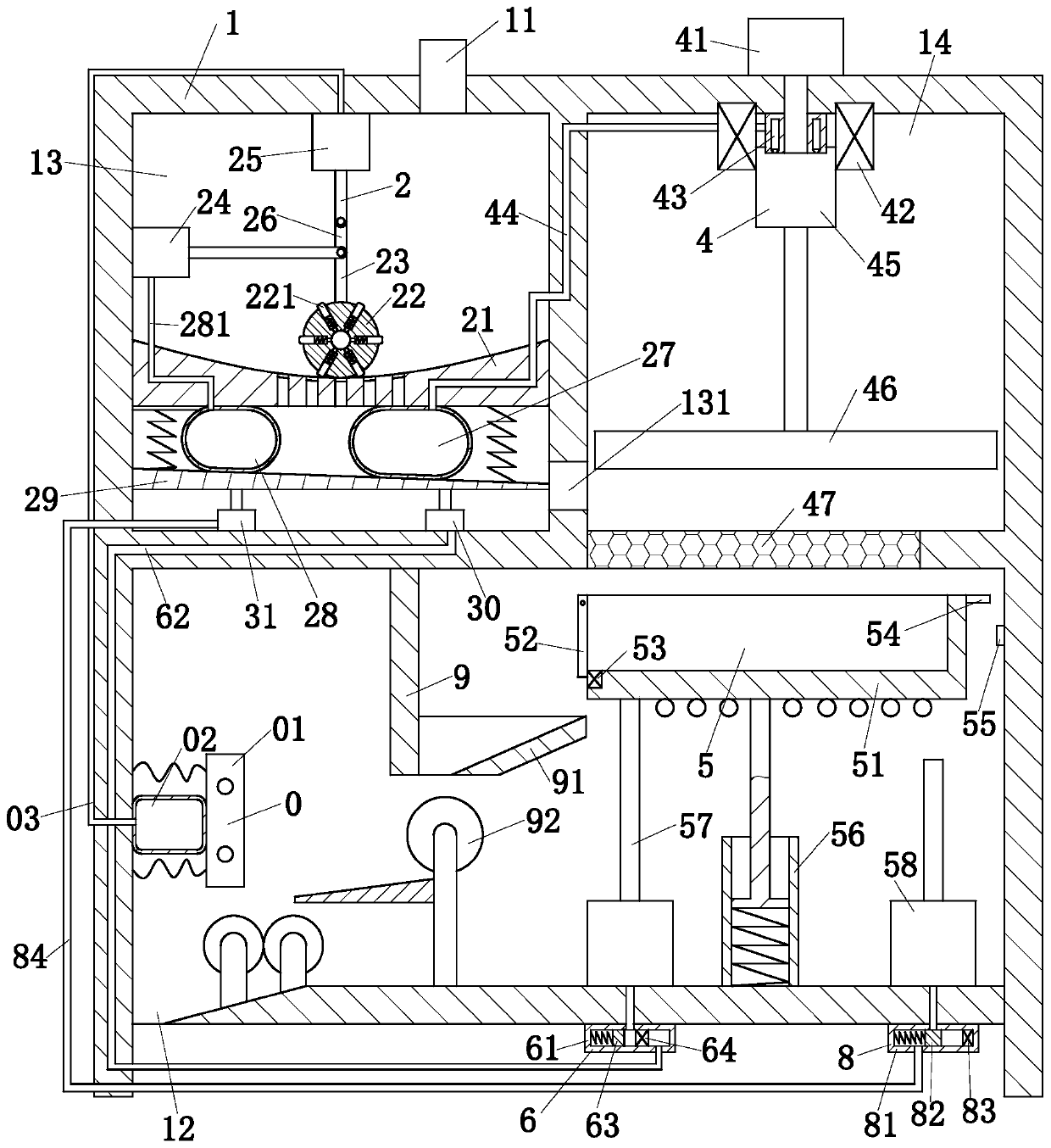
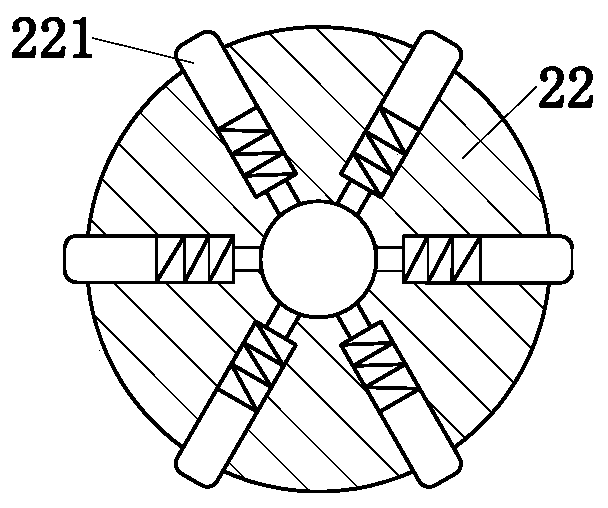
[0023] use Figure 1 to Figure 2 The smelting system of a rare earth alloy material containing a rare earth element according to an embodiment of the present invention will be described as follows.

[0024] Such as figure 1 As shown, a rare earth alloy material smelting system according to the present invention includes a sealed housing 1, a rolling module 2, a crushing module 4, a smelting module 5, a conveying module 9, a cooling module 0 and a cutting mechanism; the sealed housing The upper end of the body 1 is provided with a feed port 11, the lower end of the sealed housing 1 is provided with a discharge port 12, and a horizontal partition is provided in the sealed housing 1. The horizontal partition divides the sealed housing 1 into an upper chamber and a lower chamber. Chamber; the horizontal partition is vertically arranged with a vertical plate; the vertical plate divides the upper chamber into a left chamber 13 and a right chamber 14, and the lower end of the vertical p...


PUM


Abstract

The invention belongs to the technical field of alloy smelting, and in particular relates to a rare-earth alloy material smelting system. The rare-earth alloy material smelting system comprises a sealed shell body, a grinding module, a crushing module, a smelting module, a conveying module, a cooling module and a cutting mechanism, wherein a horizontal separation plate is arranged in the sealed shell body; the horizontal separation plate is used for separating the sealed shell body into an upper chamber and a lower chamber; the horizontal separation plate is vertically provided with a verticalplate; the vertical plate is used for separating the upper chamber into a left chamber and a right chamber; a material leakage hole for communicating the left chamber and the right chamber is formedin the lower end of the vertical plate; the grinding module is located in the left chamber; the crushing module is located in the right chamber; the smelting module is located below the crushing module; the conveying module is located below the smelting module; the cooling module is located beside the conveying module; the cutting module is located below the cooling module. By adopting the rare-earth alloy material smelting system, the crushing and smelting efficiency of a rare-earth alloy material can be improved, and the quality of the rare-earth alloy material is effectively improved.

Description

Technical field [0001] The invention belongs to the technical field of alloy smelting, and specifically is a rare earth alloy material smelting system. Background technique [0002] Rare earth has the reputation of "industrial vitamin" and has now become an extremely important strategic resource. Rare earth materials are widely used in oil, chemical, metallurgy, textile, ceramics, glass, permanent magnet materials and other fields. With the advancement of science and technology and continuous breakthroughs in application technology, the value of rare earth oxides will increase. Rare earth materials need to be crushed before smelting. In order to ensure the crystal structure and material properties of the alloy materials after smelting, the alloy materials are usually cooled. Due to the high raw material cost of rare earth alloy materials, traditional smelting equipment has a high raw material waste rate, crushing and smelting are also carried out separately, and the process tran...

Claims


Application Information

Patent Timeline
Patent Type & Authority Patents(China)
IPC IPC(8): C22C1/02C22C28/00B02C4/10B02C4/02B02C18/10B02C21/00
CPCB02C4/02B02C4/10B02C18/10B02C21/00C22C1/02C22C28/00
Inventor 王康
Owner 丹阳市佳恒特种合金材料有限公司
Why Eureka
Try Eureka