Magnetron sputtering equipment and method for removing oxide layer on substrate

A technology of magnetron sputtering and oxide layer, which is applied in sputtering plating, coating, metal material coating process, etc., can solve the problems of panel performance and quality deterioration, affecting signal conduction, etc.

Active Publication Date: 2020-11-24
WUHAN CHINA STAR OPTOELECTRONICS SEMICON DISPLAY TECH CO LTD
View PDF6 Cites 0 Cited by
  • Summary
  • Abstract
  • Description
  • Claims
  • Application Information

AI Technical Summary

Problems solved by technology

[0005] The invention provides a magnetron sputtering device and a method for removing an oxide layer on a substrate through the magnetron sputtering device, which can effectively solve the problem of the formation of an oxide layer on the surface of a substrate in an atmospheric environment in the prior art, which will affect signal transmission and cause panel Technical problems of poor performance and quality

Method used


Image

  • Magnetron sputtering equipment and method for removing oxide layer on substrate
  • Magnetron sputtering equipment and method for removing oxide layer on substrate
  • Magnetron sputtering equipment and method for removing oxide layer on substrate

Examples


Embodiment Construction

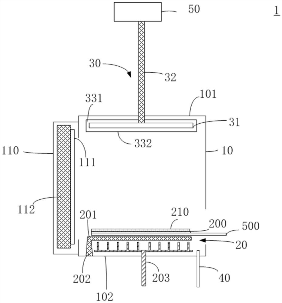
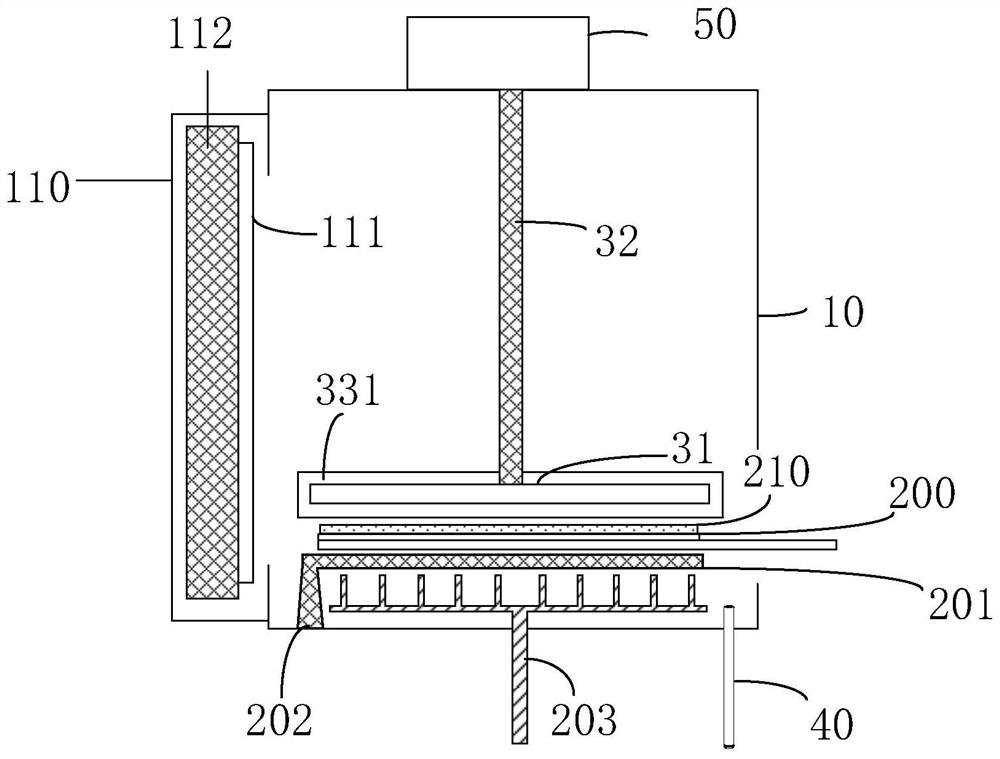
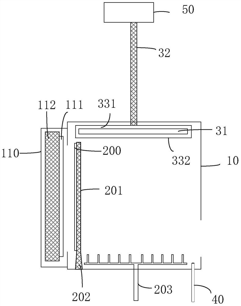
[0031] The following descriptions of the various embodiments refer to the accompanying drawings to illustrate specific embodiments in which the invention may be practiced. The directional terms mentioned in the present invention, such as [top], [bottom], [front], [back], [left], [right], [inside], [outside], [side], etc., are only for reference The orientation of the attached schema. Therefore, the directional terms used are used to illustrate and understand the present invention, but not to limit the present invention. In the figures, structurally similar elements are denoted by the same reference numerals.

[0032] The implementation process of the embodiment of the present invention will be described in detail below in conjunction with the accompanying drawings.

[0033] Generally, thin film deposition as used herein refers to the process of coating a substrate with a sputtered material. Herein, the term "coating" is used synonymously with the term "deposition". The ter...


PUM


Abstract

The invention provides magnetron sputtering equipment, which comprises a vacuum cavity, a substrate supporting component, a magnetron component, a gas supply pipeline and an additional power supply, wherein the substrate supporting component is used for bearing the substrate, and the surface of the substrate is provided with an oxidization layer; the magnetron component is provided with a first magnetic field unit and a lifting unit, and the magnetron component is driven by the lifting unit to move in an area corresponding to the substrate in the vacuum cavity; the gas supply pipeline suppliesthe vacuum cavity with gas; the additional power supply is coupled to the magnetron component and is used for applying voltage to the first magnetic field unit, and the additional power supply is applied to the first magnetic field unit to enable gas to form plasma to bombard the oxidization layer so as to break the oxidization layer. In addition, the invention also provides a method for removingthe oxidization layer on the substrate through the magnetron sputtering equipment, and is used for removing the oxidization layer on the substrate before a film deposition technology is carried out.

Description

technical field [0001] The invention relates to the technical field of liquid crystal display, in particular to a magnetron sputtering device and a method for removing an oxide layer on a substrate, which are used to effectively eliminate the oxide layer on the surface of the substrate and improve the quality and performance of display devices. Background technique [0002] The formation of layers with high uniformity (ie uniform thickness over a wide surface) on substrates is an important issue in many technical fields. For example, in the process of manufacturing thin film transistors (Thin film transistor, TFT), it is necessary to form display metal lines or interconnect semiconductors to conduct signals. The control lines required by TFT are composed of multi-layer metal thin films and semiconductor lines, and cannot be completed at one time. Most metal thin films are completed by sputtering in a vacuum chamber, and an oxide film is easily formed on the surface of the s...

Claims


Application Information

Patent Timeline
Patent Type & Authority Patents(China)
IPC IPC(8): C23C14/35C23C14/02
CPCC23C14/022C23C14/35
Inventor 谢晓龙
Owner WUHAN CHINA STAR OPTOELECTRONICS SEMICON DISPLAY TECH CO LTD
Why Eureka
Try Eureka