Food machine
A technology for a food processor and a motor shaft, which is applied in the field of food processors, can solve problems such as uneven heating and increased cost, and achieve the effects of improving heating uniformity, increasing reliability, and expanding coverage.
- Summary
- Abstract
- Description
- Claims
- Application Information
AI Technical Summary
Problems solved by technology
Method used
Image
Examples
Embodiment approach 1
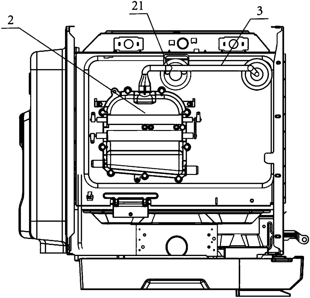
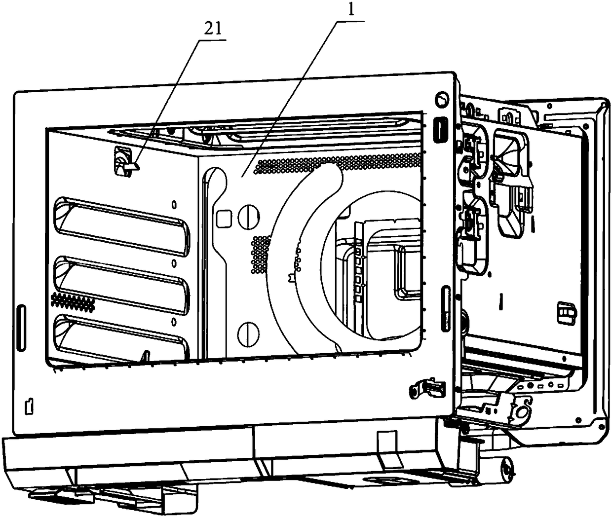
[0054] The first embodiment of the present invention provides a food cooking machine, combined figure 1 , figure 2 shown, including:
[0055] chamber 1;
[0056] A steam generating device 2, the steam generated by the steam generating device 2 is introduced into the cavity 1 through the steam nozzle 21;
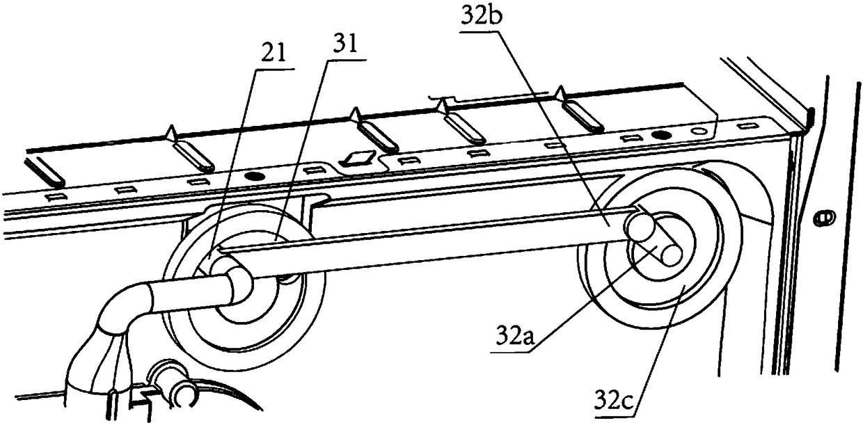
[0057] The regulating device 3 is connected with the steam spray pipe 21 and drives the steam spray pipe 21 to move, thereby adjusting the direction of the steam ejected from the steam spray pipe 21 .
[0058] It is clear to those skilled in the art that the adjustment device 3 can be composed of any power mechanism plus a transmission assembly 32 for adjusting the movement of the steam spray pipe 21 .
[0059] For example, typically, a cylinder can be set as a power mechanism, and the steam spray pipe 21 is driven to reciprocate in the horizontal direction through a connecting rod. Even, the steam generating device 2 can be connected with the cylinder as the gas source ...
Embodiment approach 2
[0079] The second embodiment of the present invention provides a food cooking machine, the embodiment of the present invention is different from the first embodiment; the main difference is that, see image 3 As shown, in the first embodiment of the present invention, the nozzle track 31 is an arc-shaped nozzle track 31, and in the second embodiment of the present invention, see Figure 9 As shown, the nozzle track 31 is a circular nozzle track 31 , and the steam nozzle 21 moves in a circle along the nozzle track 31 .
[0080] When selecting circular nozzle track 31 for use, refer to Figure 9 , Figure 6 , Figure 7 As shown, when the steam nozzle 21 is located at the left and right ends of the circular nozzle track 31, the steam will be sprayed on the food surface located on the outside and inside of the cavity 1; When the top of the middle, see Figure 8 As shown, the steam will be sprayed to the farthest distance from the steam nozzle 21 , that is, the food surface on ...
Embodiment approach 3
[0083] The third embodiment of the present invention provides a food cooking machine, and the embodiment of the present invention is different from the first embodiment; the main difference is that, see Figure 9 As shown, in the first embodiment of the present invention, the nozzle connecting rod 32b is connected with the motor connecting rod 32a, guided and connected by the circular track 32c and the protrusion 32d embedded in the circular track 32c, and in the present invention For a second implementation of , see Figure 11 As shown, the nozzle connecting rod 32b is connected to the turntable 32e, and is guided by the turntable 32e. Specifically, the transmission assembly 32 includes:
[0084] The turntable 32e is sleeved on the motor shaft and can rotate under the drive of the motor shaft;
[0085] Spray pipe connecting rod 32b, one end is connected with steam spray pipe 21, and the other end is connected on the turntable 32e;
[0086] Driven by the motor shaft, the tu...
PUM
 Abstract
Description
Claims
Application Information
 - R&D
- Intellectual Property
- Life Sciences
- Materials
- Tech Scout
- Unparalleled Data Quality
- Higher Quality Content
- 60% Fewer Hallucinations
Browse by: Latest US Patents, China's latest patents, Technical Efficacy Thesaurus, Application Domain, Technology Topic, Popular Technical Reports.
© 2025 PatSnap. All rights reserved.Legal|Privacy policy|Modern Slavery Act Transparency Statement|Sitemap|About US| Contact US: help@patsnap.com


