Method for controlling pressure in gas-liquid dynamic testing device

A dynamic test and pressure technology, applied in soil material testing, material inspection products, etc., can solve problems such as difficulty in automatically controlling pressure, inability to directly measure contact angle, and inability to observe phase interfaces.

Active Publication Date: 2019-01-01
INST OF MECHANICS - CHINESE ACAD OF SCI
View PDF4 Cites 0 Cited by
  • Summary
  • Abstract
  • Description
  • Claims
  • Application Information

AI Technical Summary

Problems solved by technology

However, the dynamic displacement process means that the phase interface will move a certain distance, so the high-magnification microscope cannot observe the movement process of the phase interface
[0004] If a low magnification microscope is used to observe, the change of the position of the phase interface can be observed, but the phase interface cannot be observed, so the contact angle cannot be directly measured
[0005] In addition, the pressure of the existing test liquid cannot be quantified, and it is not easy to adjust the pressure through automatic control to meet the predetermined target pressure

Method used


Image

  • Method for controlling pressure in gas-liquid dynamic testing device
  • Method for controlling pressure in gas-liquid dynamic testing device
  • Method for controlling pressure in gas-liquid dynamic testing device

Examples


Embodiment Construction

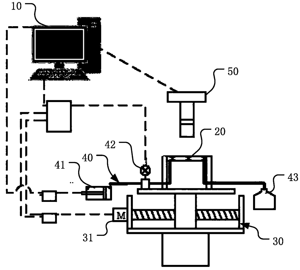
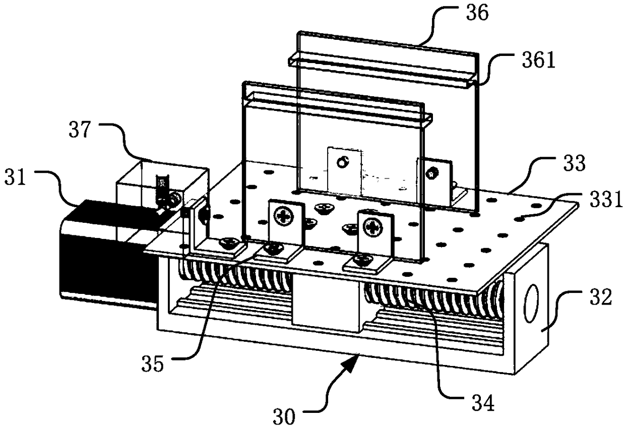
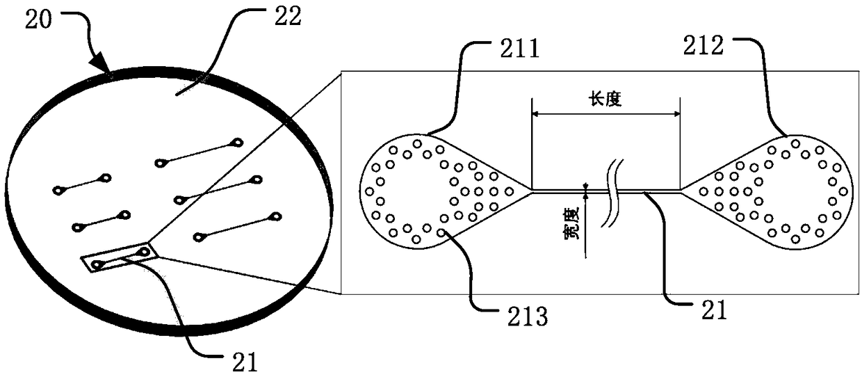
[0032] Such as figure 1 , 2 , 3, the present invention provides a method for controlling the pressure in a gas-liquid dynamic testing device, which generally includes a microfluidic chip 20, a pressure control pipeline 40, a mobile platform 30, a camera unit 50 and a control system 10.

[0033] The microfluidic chip 20 is used for passing the test liquid, and is provided with a micron capillary channel 21; the specific microfluidic chip 20 can be a plate-shaped structure made of glass, organic material, or the like. The micron capillary channel 21 is the place where gas-liquid dynamic two-phase displacement occurs, and it needs to have sufficient strength, processing accuracy and operability. According to the requirements of this embodiment, the characteristic size of the microcapillary channel 21 is in the range of 10-100 μm, such as 20, 40 and 80 μm used in this embodiment, and tested respectively.

[0034] Concrete microfluidic chip 20 can adopt polydimethylsiloxane (PDMS...


PUM

PropertyMeasurementUnit
elastic modulusaaaaaaaaaa

Abstract

The invention provides a method for controlling the pressure in a gas-liquid dynamic testing device. Through the dynamic measuring device, the current pressure is obtained; then, the relationship withthe flow rate is determined by using the pressure; further, the target pressure is met through controlling the flow rate. Through the flow rate control on the gas-liquid two-phase flowing process ina capillary vessel in a micrometer scale, the control on the test liquid pressure is realized, so that the basis is provided for the obtaining the precise dynamic contact angle under the conditions ofsmall capillary vessel quantity and low Bond number states; the control flow process is simplified; the data processing efficiency and the measurement precise are greatly improved.

Description

technical field [0001] The invention relates to the field of enhanced petroleum exploitation, in particular to a method for measuring the gas-liquid dynamic displacement process in the micron capillary, which can adjust the target pressure in the micron capillary channel by testing the flow rate of the liquid. Background technique [0002] The mechanism of two-phase displacement in a single micron-scale capillary is the basis of two-phase displacement in porous media in natural environments. Two-phase displacement in porous media occurs in many industrial or natural processes, such as water in tight oil reservoirs. For processes such as gas flooding, solution gas flooding, and water flooding, obtaining dynamic contact angle information under the above industrial conditions is crucial for evaluating the two-phase displacement process in the entire porous medium. [0003] Many experiments in the prior art have realized the scheme of measuring the dynamic contact angle in a cap...

Claims


Application Information

Patent Timeline
Patent Type & Authority Applications(China)
IPC IPC(8): G01N33/24
CPCG01N33/24
Inventor 雷达林缅江文滨曹高辉徐志朋李曹雄姬莉莉
Owner INST OF MECHANICS - CHINESE ACAD OF SCI
Why Eureka
Try Eureka