Check patentability & draft patents in minutes with Patsnap Eureka AI!

A magnetically enhanced plasma source

A plasma source, enhanced technology, applied in the field of plasma, can solve the problems of surface source processing requiring high precision, affecting the quality and uniformity of the coating, increasing the cost of equipment use, etc., achieving not easy partial discharge and long service life. , the effect of increasing the probability of collision

Active Publication Date: 2020-10-02
上海硕余精密机械设备有限公司
View PDF5 Cites 0 Cited by
  • Summary
  • Abstract
  • Description
  • Claims
  • Application Information

AI Technical Summary

Problems solved by technology

The problem of planar plasma sources in the prior art is that the processing of the planar source itself requires high precision and high processing costs. Since the planar source corresponds to a large horizontal cross-sectional area of ​​the vacuum chamber, the radio frequency power supply used in conjunction with it High power, high power of RF power supply, it will easily form local high voltage discharge, cause local damage and reduce service life
The problem with the microwave linear plasma source is that the quartz tube needs to be replaced regularly. The service life of the quartz tube is between 60-120 hours, which significantly increases the cost of the equipment and shortens the life cycle of the equipment.
The common problem of the above two linear plasma sources is that during the plasma coating process, it is easy to cause deposits to block the pores, and the gas output of the pores is not uniform, which affects the quality and uniformity of the coating.

Method used


Image

  • A magnetically enhanced plasma source
  • A magnetically enhanced plasma source
  • A magnetically enhanced plasma source

Examples


Embodiment Construction

[0021] In order to make the purpose, technical solution and advantages of the present invention clearer, the specific implementation manners of the present invention will be further described in detail below in conjunction with the accompanying drawings.

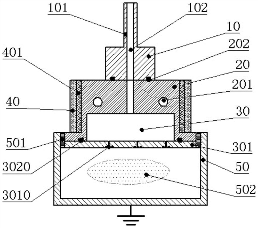
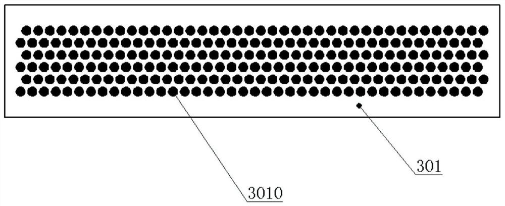
[0022] Please refer to the attached figure 1 , a magnetically enhanced plasma source provided by the present invention includes a cover plate 20, a buffer chamber 30, a magnetic enhancement module 40 and an air intake module 10; the cover plate 20 contains a hollow buffer chamber 30, and the buffer chamber 30 The lower surface of the lower surface of the buffer chamber 30 is flush with the lower surface of the cover plate 20, and the surface of the buffer chamber 30 is surrounded by the cover plate 20 except the lower surface, and the lower surface of the cover plate 20 and the buffer chamber 30 is connected to the ground through the gas distribution plate 301. Vacuum chamber 50; Gas outlet unit 3010 is distributed on the ga...


PUM


Abstract

The invention discloses a magnetically enhanced plasma source. The magnetically enhanced plasma source includes a cover plate, a cushion chamber, a magnetic enhancement module and an air inlet module,wherein the hollow cushion chamber is arranged in the cover plate; the lower surface of the cover plate and the lower surface of the cushion chamber are connected to a grounded vacuum chamber througha gas distribution plate; gas outlet units are distributed on the gas distribution plate; the magnetic enhancement module comprises an insulating plate and a magnet block; the magnet block is isolated from the cover plate through the insulating plate; the air inlet module is located above the cover plate, and includes at least one electrode interface which is located on the upper surface of the air inlet module; an air inlet pipe is arranged in the electrode interface; and the air inlet pipe penetrates through the electrode interface, the air inlet module and the cover plate to extend into the cushion chamber. The magnetically enhanced plasma source can effectively avoid deposits blocking air outlets, can improve the ionization rate of the reaction gas, and can prolong the service life ofthe plasma source.

Description

technical field [0001] The invention relates to plasma technology, in particular to a magnetically enhanced plasma source. Background technique [0002] With the advancement of science and technology, more and more technologies are applied to plasma in the manufacturing process of solar cells, liquid crystal panels and semiconductor chips, especially plasma etching and plasma coating technologies. The core component for generating plasma is the plasma source. According to the shape of the plasma source, the plasma source can be divided into point source, linear source and surface source. Among them, the point source refers to the generation of plasma at one or more points; the linear source refers to the one-dimensional The plasma is generated in a strip area; the planar source refers to the generation of plasma in a two-dimensional plane area. Generally, the linear source and the planar source are only distinguished in the aspect ratio of the plasma generating region, and...

Claims


Application Information

Patent Timeline
Patent Type & Authority Patents(China)
IPC IPC(8): H01J37/32
CPCH01J37/3244H01J37/3266
Inventor 陈韦斌张垒
Owner 上海硕余精密机械设备有限公司
Features
  • R&D
  • Intellectual Property
  • Life Sciences
  • Materials
  • Tech Scout
  • Unparalleled Data Quality
  • Higher Quality Content
  • 60% Fewer Hallucinations
Learn More