Working method of switch cabinet with self-cleaning function

A working method and switchgear technology, which is applied in the field of switchgear, can solve the problems that the air cleaning device does not have self-cleaning, it is difficult to intelligently control the switchgear, and the self-cleaning of the switchgear cannot be achieved, so as to achieve convenient power supply, solve power consumption problems, The effect of high work efficiency

Active Publication Date: 2019-01-01
ANHUI WANXIANG ELECTRIC POWER EQUIP
View PDF7 Cites 5 Cited by
  • Summary
  • Abstract
  • Description
  • Claims
  • Application Information

AI Technical Summary

Problems solved by technology

[0005] However, there are great defects in heat dissipation in this result, and the air cleaning device does not have the function of self-cleaning, so that the switchgear cannot be self-cleaned well; in addition, the application number is 201410179546.8 patent "intelligent power-saving Switchgear", the intelligent means used in the switchgear have been difficult to carry out the intelligent control of the current switchgear, and there are great deficiencies in power saving and heat dissipation

Method used


Image

  • Working method of switch cabinet with self-cleaning function
  • Working method of switch cabinet with self-cleaning function
  • Working method of switch cabinet with self-cleaning function

Examples


Embodiment

[0040] see Figure 1 to Figure 11 , the present invention provides a technical solution:

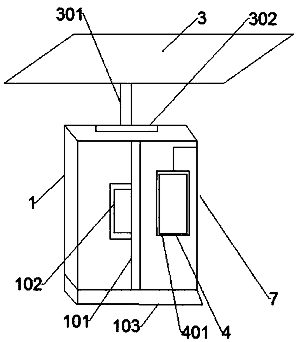
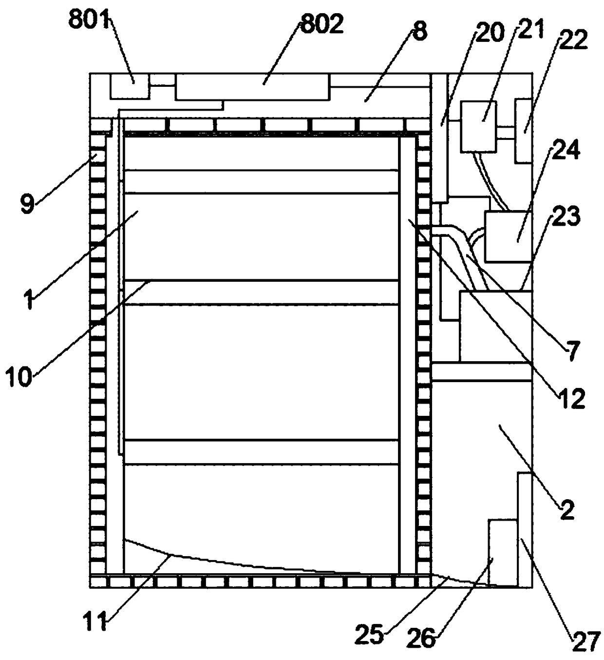
[0041] A switchgear with self-cleaning function, including a cabinet body 1, the front end of the cabinet body 1 is provided with a cabinet door 101 opened by a handle 102, and it is characterized in that it also includes a cleaning tank 2 arranged in the cabinet body and a cleaning tank fixed on the cabinet body 1 The solar panel 3 at the upper end;

[0042] The front end of the cabinet body 1 is also equipped with a main control board 4, and a temperature sensor 404 and a PLC main controller 403 are installed in the main control board 4. The temperature sensor 404 is electrically connected with the PLC main controller 403, and the PLC main controller 403 is 402 power supply;

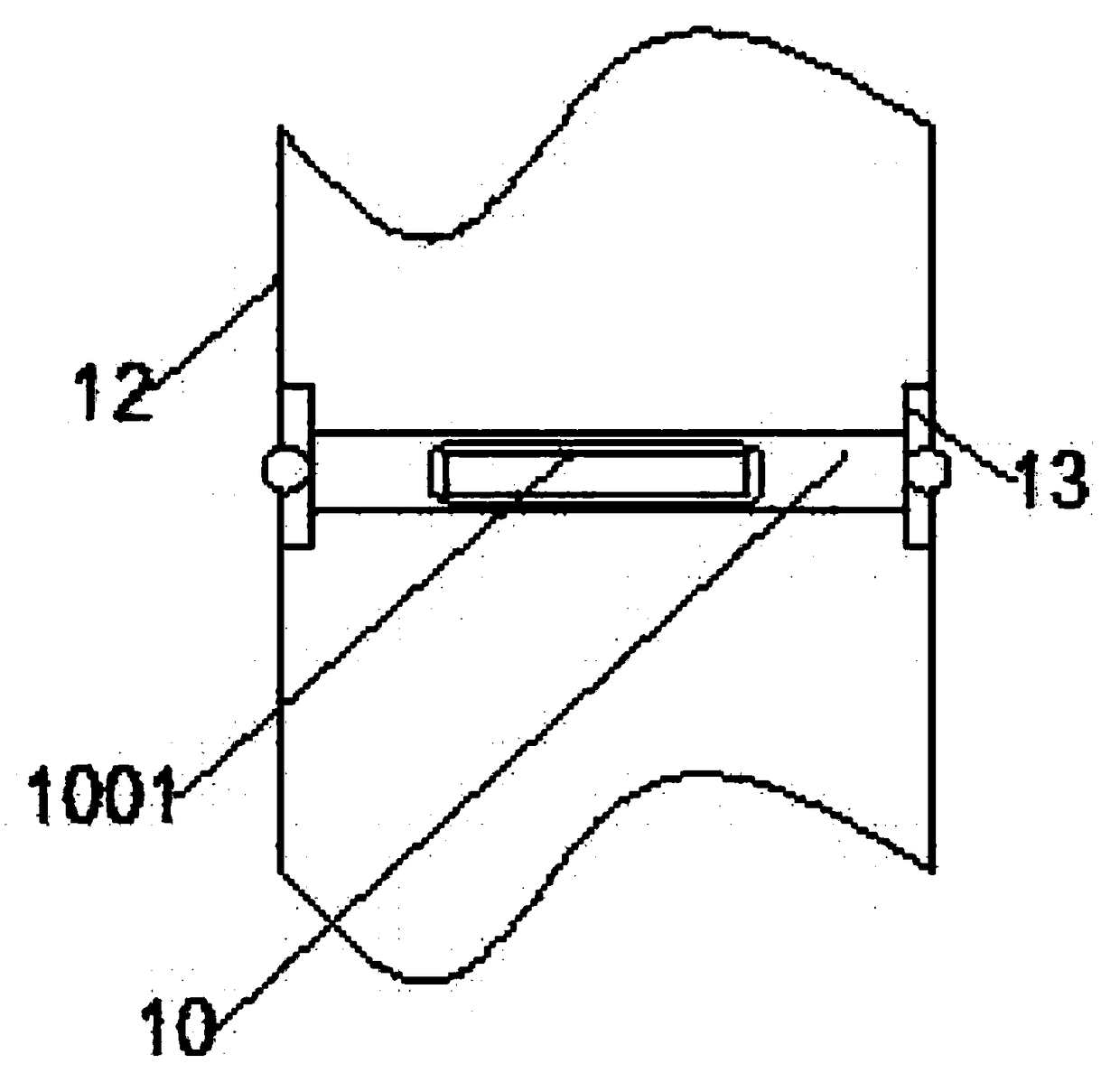
[0043] Inside the cabinet body 1 are provided with two vertical chute 12, three placement boards 10 are installed between the chute 12 at both ends, the two ends of the placement board 10 are slidingly connecte...


PUM


Abstract

The invention discloses a switch cabinet with a self-cleaning function, and the switch cabinet comprises a cabinet body. The front end of the cabinet body is provided with a cabinet door which is opened through a handle. The switch cabinet also comprises a cleaning groove disposed in the cabinet body, and a solar panel fixed at the upper end of the cabinet body. The front end of the cabinet body is provided with a main control board, and the interior of the main control board is provided with a temperature sensor and a PLC main controller. The temperature sensor is electrically connected withthe PLC main controller, and the PLC main controller is powered by a storage battery. The interior of a lateral hollow groove is provided with a power storage tank, and the power storage tank is electrically connected with a solar panel through a photovoltaic controller. The interior of a vertical hollow groove is provided with a power supply main board, a dust collector and an electric ventilation butterfly valve. The dust collector and the electric ventilation butterfly valve are fixed at the center in the cleaning groove through a fixed plate. One end of an electric valve is provided with awater level sensor. The cabinet can achieve the resistance to dust, can achieve the intelligent control of the heat dissipation of the interior, combines the heat dissipation and the cleaning, enables the internal temperature in the switch cabinet to be moderate, and is convenient in power supply.

Description

[0001] This application is a divisional application of the invention patent application with the application number 2017105394450. technical field [0002] The invention relates to the technical field of switch cabinets, in particular to a switch cabinet with a self-cleaning function. Background technique [0003] The switch cabinet is a kind of electrical equipment. The outside line of the switch cabinet first enters the main control switch in the cabinet, and then enters the sub-control switch. Each branch is set according to its needs. Such as instruments, automatic controls, motor magnetic switches, various AC contactors, etc., some also have high-voltage room and low-voltage room switch cabinets, high-voltage busbars, such as power plants, etc. load shedding. [0004] Traditional switch cabinets are very cumbersome to clean. With the development of society, great attention has been paid to the cleaning of switch cabinets. At present, some progress has been made, such a...

Claims


Application Information

Patent Timeline
Patent Type & Authority Applications(China)
IPC IPC(8): H02B1/30H02B1/28H02B1/56H02J7/35
CPCH02B1/28H02B1/30H02B1/301H02B1/565H02J7/35Y02A30/14Y02E10/56
Inventor 段建英李岚吴翔天
Owner ANHUI WANXIANG ELECTRIC POWER EQUIP
Why Eureka
Try Eureka