A deep condensation recovery device for high-concentration organic waste gas

A technology of organic waste gas and deep condensation, applied in steam condensation, gas treatment, separation methods, etc., can solve the problems of carbon bed not being able to dissipate heat in time, low emission concentration, explosion, etc., and achieve improved adsorption treatment effect, low emission concentration, and improved The effect of the factor of safety

Active Publication Date: 2020-11-06
WUXI ZHONGTIAN SOLID WASTE DISPOSAL CO LTD
View PDF5 Cites 0 Cited by
  • Summary
  • Abstract
  • Description
  • Claims
  • Application Information

AI Technical Summary

Problems solved by technology

[0005] Aiming at the shortcomings of the above-mentioned existing production technology, the applicant provides a deep condensation recovery device for high-concentration organic waste gas, so as to effectively solve the problem of heat accumulation in the process of waste gas being adsorbed, which leads to the failure of timely heat dissipation inside the fixed bed and the occurrence of carbon bed fire or Explosion problems, making it stable in operation, good recovery effect, high safety performance, low emission concentration

Method used


Image

  • A deep condensation recovery device for high-concentration organic waste gas

Examples


Embodiment 1

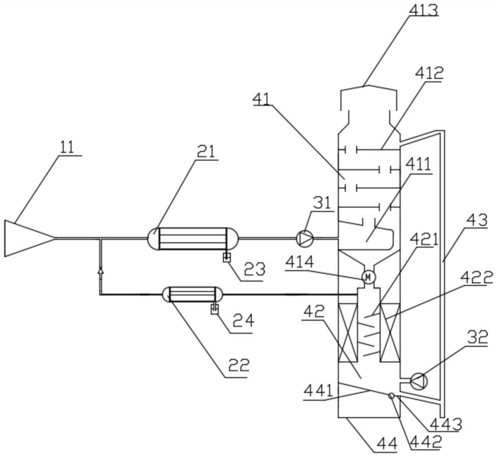
[0051] (1) The discharge outlet of an oil tank at a wharf, with a processing capacity of 500m 3 / h, oil and gas content 125g / m3;

[0052] (2) Five wide-mouth gas collecting hoods are used for collection, with a processing capacity of 500m 3 / h, the deep condenser is designed to condense at -40°C, the normal temperature cooler 22 is set to condense at 20°C, and the oil and gas are condensed to liquid and then recovered. The air flow passes through the bottom fan (520m 3 / h) Quantitative flow to the fluidized adsorption zone 41.

[0053] (3) The fluidized adsorption zone 41 selects a spherical adsorbent as the adsorbent, and the diameter of the adsorbent is less than or equal to 0.6 mm. The four-layer pore sieve plate 412 has a plate thickness of 2 mm. Small holes are evenly opened on the plate, the opening rate is 10%, and the floor height is 300 mm. , arranged in an equilateral triangle, the diameter of the small hole is 2.4mm, there is an overflow cofferdam on the left sid...

Embodiment 2

[0057] (1) The discharge outlet of an oil tank at a gas station, with a processing capacity of 200m 3 / h, oil and gas content 100g / m 3 ;

[0058] (2) Use a wide-mouth gas collecting hood for collection, and the constant air volume of the fan is 90m 3 / h, the deep condenser is designed to condense at -40°C, the normal temperature cooler is set to condense at 20°C, and the oil and gas are condensed to liquid and then recovered. The air flow passes through the bottom fan (210m 3 / h) Quantitative flow to the fluidized adsorption zone 41.

[0059] (3) Spherical adsorbent is selected as the adsorbent in the fluidized adsorption zone 41, the diameter of the adsorbent is ≤0.6mm, the three-layer pore sieve plate 412, the plate thickness is 2mm, small holes are uniformly opened on the plate, the opening rate is 10%, and the layer height is 300mm , arranged in an equilateral triangle, the diameter of the small hole is 2.4mm, there is an overflow cofferdam on the left side, the height...


PUM


Abstract

The invention relates to a high-concentration volatile organic compound deep condensation recovery device which comprises a bin and an intake collection system. A purified gas outlet is formed in thetop of the bin, a fluidized adsorption zone is arranged on the upper portion of the bin, a rotatable discharging valve is mounted at the bottom of the fluidized adsorption zone, a high-temperature desorption zone is arranged below the rotatable discharging valve, the output end of the intake collection system are divided into two branches, one branch is sequentially connected with a low-temperature deep condensation device and an adsorption intake system through pipelines, the adsorption intake system is communicated with the fluidized adsorption zone, the other branch is connected with a normal-temperature cooler through a pipeline, and the normal-temperature cooler is communicated with a channel. The recovery device effectively solves the problems that heat accumulation is formed when exhaust gas is adsorbed, so that the inside of a fixed bed cannot be timely cooled, and a carbon bed catches fire or explodes. The device is stable in running, better in recovery effect, high in safetyand low in emission concentration.

Description

technical field [0001] The invention relates to the technical field of recovery equipment, in particular to a deep condensation recovery device for high-concentration organic waste gas. Background technique [0002] In the process of production, storage, transportation and sales, it is inevitable to produce some high-concentration organic waste gas, such as gas stations, docks, petrochemical plants, pharmaceutical workshops, etc. The direct discharge of exhaust gas into the atmosphere not only causes energy waste, but also brings serious environmental pollution and safety hazards. [0003] Common organic vapor recovery methods mainly include adsorption method, absorption method, membrane separation method and condensation method. The advantage of adsorption separation is that the tail gas concentration can be controlled within a very small index, but the disadvantage is that the thermal effect of adsorption is obvious. The absorption method and condensation method require l...

Claims


Application Information

Patent Timeline
Patent Type & Authority Patents(China)
IPC IPC(8): B01D5/00B01D53/02B01D53/04
CPCB01D5/00B01D53/02B01D53/0454B01D2257/70B01D2258/02
Inventor 马斌斌陈琪王婧婷郎超
Owner WUXI ZHONGTIAN SOLID WASTE DISPOSAL CO LTD
Why Eureka
Try Eureka