Single cylinder column sand maker

A technology of sand making machine and cylinder, which is applied in the direction of grain processing, etc., and can solve the problem that the side wall of the main shaft is prone to damage and other problems

Inactive Publication Date: 2019-01-04
ZAOZHUANG SNKSAN INTELLIGENT MACHINERY CO LTD
View PDF0 Cites 5 Cited by
  • Summary
  • Abstract
  • Description
  • Claims
  • Application Information

AI Technical Summary

Problems solved by technology

[0003] The object of the present invention is to provide a single-cylinder cylindrical sand making machine, which includes a transmission pipeline, a transmission auger, an outer shell and a crushing box, so as to solve the

Method used


Image

  • Single cylinder column sand maker
  • Single cylinder column sand maker
  • Single cylinder column sand maker

Examples


Embodiment 1

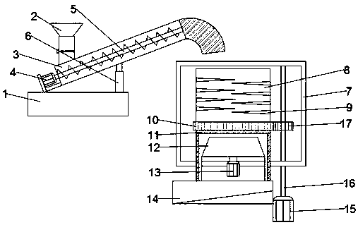
[0017] see Figure 1-2 , in the embodiment of the present invention, a single-cylinder cylindrical sand making machine includes a conveying pipeline 3, a conveying auger 5, an outer shell 7 and a crushing box 8, and the conveying pipeline 3 is used to convey sand and gravel into the crushing box 8 , and the transmission pipeline 3 is arranged obliquely, the lower end of the transmission pipeline 3 is hinged to the upper surface of the support table 1, the transmission pipeline 3 communicates with the crushing box 8, and an outer casing 7 is arranged outside the crushing box 8, and the outer casing 7 and the The crushing box 8 is rotationally connected, and the outer wall of the outer shell 7 is fixedly welded with the outer ring gear 10, and the right side of the outer ring gear 10 is provided with a first gear 17, the first gear 17 is arranged in the outer shell 7, and the second A gear 17 is fixedly welded to the rotating shaft 16, and the lower end of the rotating shaft 16 ...

Embodiment 2

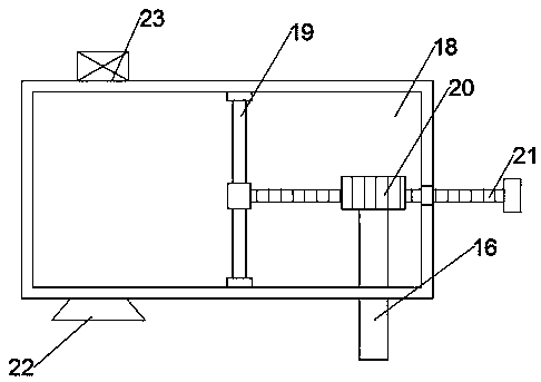
[0024] see Figure 3-4 , in an embodiment of the present invention, a dust collection assembly, a dust collection assembly 18 is arranged above the outer casing 7, the outer casing 7 is fixedly connected to the dust collection assembly 18, and a piston plate 19 is movably installed inside the dust collection assembly 18 The upper and lower ends of the piston plate 19 are slidingly connected to the inner wall of the dust collection assembly 18, the middle position of the right side wall of the piston plate 19 is welded with a rack 21, and the right end of the rack 21 runs through the right side wall of the dust collection assembly 18 , and the rack 21 is slidingly connected to the right side wall of the dust suction assembly 18, and the right half of the cavity of the dust suction assembly 18 is provided with a second gear 20, and the second gear 20 meshes with the rack 21 The upper end of the rotating shaft 16 runs through the lower wall of the dust suction assembly 18, and is...


PUM


Abstract

The invention discloses a single cylinder column sand maker, belongs to the technical field of sand making equipment and aims to solve the problem that a main shaft side wall is easily broken when being hit by gravel as a main shaft is placed inside a sand making cylinder when a conventional sand maker is used. The single cylinder column sand maker is technically characterized by comprising a conveying pipeline, a conveying packing auger, a shell and a crushing tank, wherein the conveying pipeline is used for conveying gravel into the crushing tank; the conveying pipeline is arranged in an inclined manner; the lower end of the conveying pipeline is hinged with the upper surface of a support platform; the conveying pipeline is communicated with the crushing tank; the shell is arranged outside the crushing tank; an outer tooth ring is fixedly welded with the outer wall of the shell; a first gear is arranged on the right side of the outer tooth ring. By adopting the single cylinder columnsand maker, automatic feeding can be achieved, the working intensity of operators can be alleviated, meanwhile, the gravel can be sufficiently crushed at multiple stages, and dust made in the gravelcrushing process can be prevented from being discharged, so that external environments and life security of operators can be protected, and the sand maker is applicable to popularization.

Description

technical field [0001] The invention relates to the technical field of sand making equipment, in particular to a single-cylinder cylindrical sand making machine. Background technique [0002] Sand making machine, also known as sand making machine, is an indispensable equipment in construction engineering. Sand making machine is widely used in the crushing of cement, glass raw materials, ore and corundum. The working principle of sand making machine is to combine different The stones with particle size are put into the sand making machine, and then the driving spindle inside the sand making machine drives the sand making rotor to rotate, so that the raw materials inside the sand making machine are fully mixed and crushed, and then the crushed stones are ground. Finally, the developed sand was realized. The main shaft of the existing sand making machine is placed inside the sand making cylinder when it is working. The side wall of the main shaft is easily damaged by the impact...

Claims


Application Information

Patent Timeline
IPC IPC(8): B02C21/00B02C23/02B02C18/06B02C18/12B02C18/24B02C23/10B02C4/10B02C4/30B02C23/20
CPCB02C21/00B02C4/10B02C4/30B02C18/067B02C18/12B02C18/24B02C23/02B02C23/10B02C23/20
Inventor 马驰孙启祥孙法虎
Owner ZAOZHUANG SNKSAN INTELLIGENT MACHINERY CO LTD
Why Eureka
Try Eureka