A butterfly valve welding station
What is Al technical title?
Al technical title is built by PatSnap Al team. It summarizes the technical point description of the patent document.
A welding table and butterfly valve technology, applied in welding equipment, auxiliary welding equipment, welding/cutting auxiliary equipment, etc., can solve the problems of spark spatter, inability to handle sparks, easy to cause fire, etc., to prevent spatter everywhere and eliminate the hidden danger of fire , to ensure the effect of safety
Active Publication Date: 2020-07-03
繁昌县长城铸造厂(普通合伙)
View PDF5 Cites 1 Cited by
Summary
Abstract
Description
Claims
Application Information
AI Technical Summary
This helps you quickly interpret patents by identifying the three key elements:
Problems solved by technology
Method used
Benefits of technology
Problems solved by technology
[0004] Aiming at the deficiencies of the prior art, the present invention provides a butterfly valve welding station, which solves the problem that when the welding station is in use, the sparks generated during butterfly valve welding cannot be effectively treated, causing sparks to splash everywhere, and fires are likely to be caused when sparks splash. A problem that poses a great threat to the safety of the staff
Method used
Image
Click on the blue label to locate the original text in one second.
Reading with bidirectional positioning of images and text.
Examples
Embodiment Construction
[0018] The following will clearly and completely describe the technical solutions in the embodiments of the present invention with reference to the accompanying drawings in the embodiments of the present invention. Obviously, the described embodiments are only some, not all, embodiments of the present invention. Based on the embodiments of the present invention, all other embodiments obtained by persons of ordinary skill in the art without making creative efforts belong to the protection scope of the present invention.
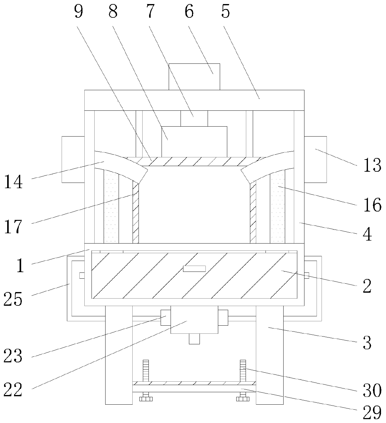
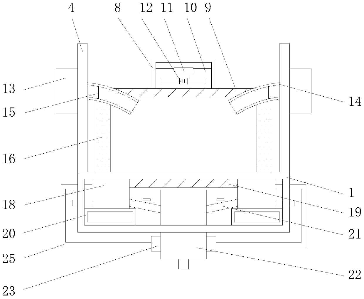
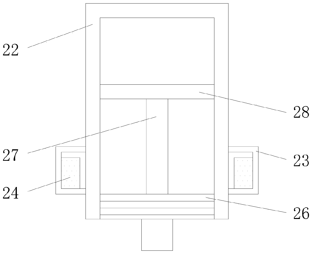
[0019] Such as Figure 1-3 As shown, the present invention provides a technical solution: a butterfly valve welding station, including a housing 1, the front of the inner top of the housing 1 is movably connected with a door panel 2 through a hinge, and both sides of the bottom of the housing 1 are fixedly connected with a support. Both sides of the leg 3 and the top of the housing 1 are fixedly connected with vertical plates 4, the tops of the two vertical pl...
PUM
Abstract
The invention discloses a butterfly valve welding table. The butterfly valve welding table comprises a shell; a door sheet is movably connected in front of the top of the inner side of the shell through a hinge; support legs are fixedly connected to two sides of the bottom of the shell; vertical plates are fixedly connected to two sides of the top of the shell; the tops of the two vertical platesare connected with the bottom of a top plate; a fog cooler is fixedly connected to the top center of the top plate; and an output end of the fog cooler is in communication connection with a conveyingpipe. Through cooperative use of the shell, the vertical plates, the too plate, the fog cooler, the conveying pipe, a cylinder, a fixed shell, a connecting rod, a motor, a fan, an air sucking machine,a bent pipe, a filter plate, a vertical pipe, a water tank, a magnet, an inclined pipe, a thick pipe, a connecting shell, a water pump, a connecting pipe, a round plate, a vertical rod and a leakageplate, the butterfly valve welding table can preferably treat sparks generated in welding of butterfly valves, prevents the spark splashing condition, and prevents hidden troubles of fire.
Description
technical field [0001] The invention relates to the technical field of welding stations, in particular to a butterfly valve welding station. Background technique [0002] The valve can be used to control the flow of various types of fluids such as air, water, steam, various corrosive media, mud, oil, liquid metal and radioactive media. It mainly plays the role of cutting and throttling on the pipeline. The opening and closing parts of the butterfly valve are A disc-shaped butterfly plate rotates around its own axis in the valve body to achieve the purpose of opening and closing or adjustment. During the production and processing of the butterfly valve, a welding station is also needed to weld the various parts of the butterfly valve, further increasing The quality and firmness of the butterfly valve, but when the welding station is in use today, it cannot effectively deal with the sparks generated during the welding of the butterfly valve, causing the sparks to splash everyw...
Claims
Application Information
Patent Timeline
Application Date:The date an application was filed.
Publication Date:The date a patent or application was officially published.
First Publication Date:The earliest publication date of a patent with the same application number.
Issue Date:Publication date of the patent grant document.
PCT Entry Date:The Entry date of PCT National Phase.
Estimated Expiry Date:The statutory expiry date of a patent right according to the Patent Law, and it is the longest term of protection that the patent right can achieve without the termination of the patent right due to other reasons(Term extension factor has been taken into account ).
Invalid Date:Actual expiry date is based on effective date or publication date of legal transaction data of invalid patent.