
Production line for manufacturing S connecting pipe

A production line and pipe section technology, applied in the field of pipe fittings processing and forming equipment, can solve the problems of low processing efficiency and low degree of automation, and achieve the effects of improving production efficiency, reducing chip generation, and reducing manual handling and other processes

Active Publication Date: 2019-01-04
浙江长兴和良智能装备有限公司
View PDF12 Cites 3 Cited by
  • Summary
  • Abstract
  • Description
  • Claims
  • Application Information

AI Technical Summary

Problems solved by technology

[0003] When manufacturing the S-joint with the above-mentioned structure, it is usually necessary to use a cutting device to cut the long pipe material into fixed-length pipe sections, and then transport these fixed-length pipe sections to the pipe section processing unit for loading, so as to process the ends according to the predetermined structure. Pipe end treatment, and then transfer the pipe section after pipe end treatment to the punching device for punching processing. The whole processing process has a low degree of automation and low processing efficiency.

Method used


Image

  • Production line for manufacturing S connecting pipe
  • Production line for manufacturing S connecting pipe
  • Production line for manufacturing S connecting pipe

Examples


Embodiment Construction

[0033] The present invention will be further described below in conjunction with embodiment and accompanying drawing.

[0034] Example of production line

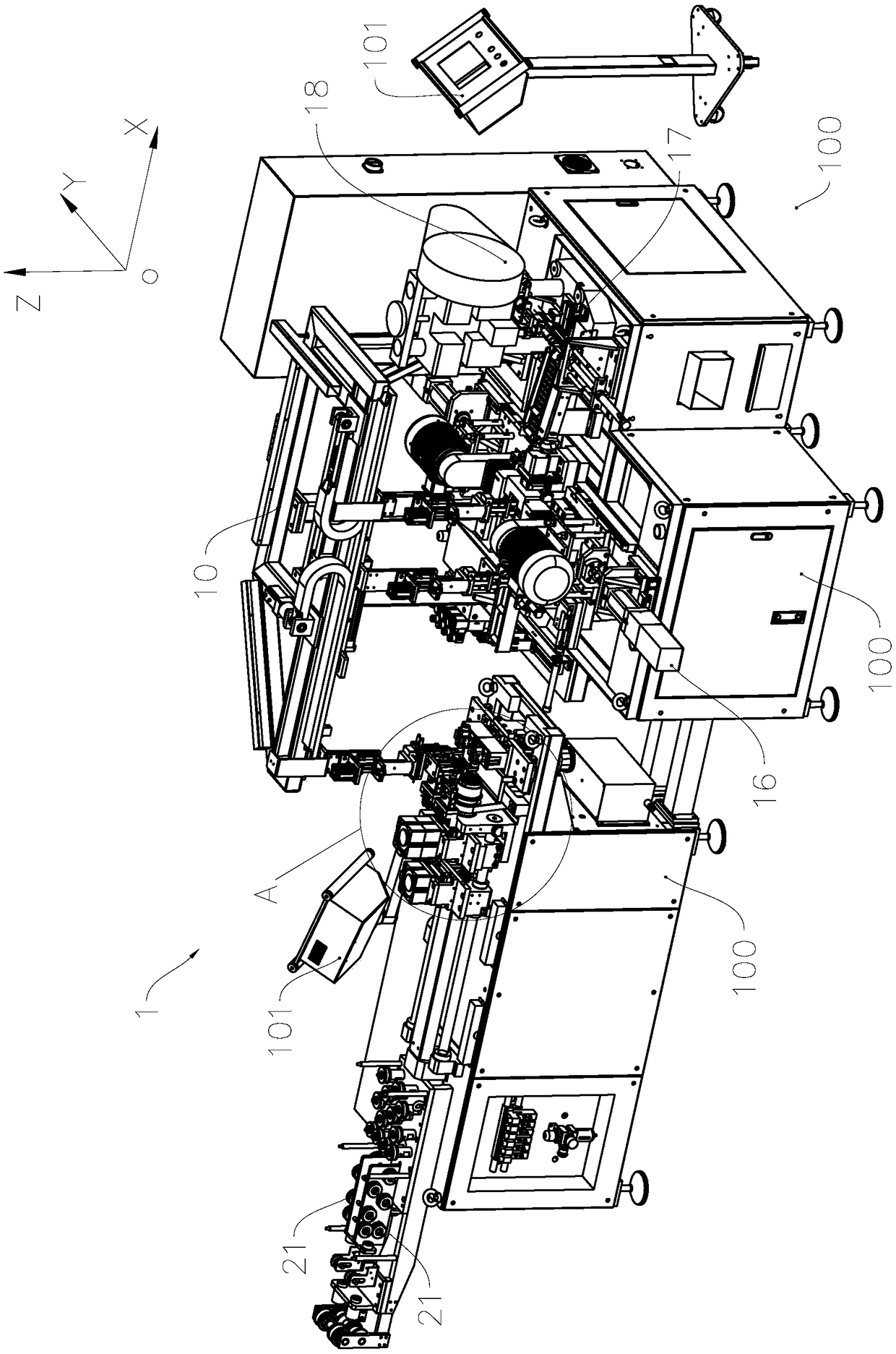
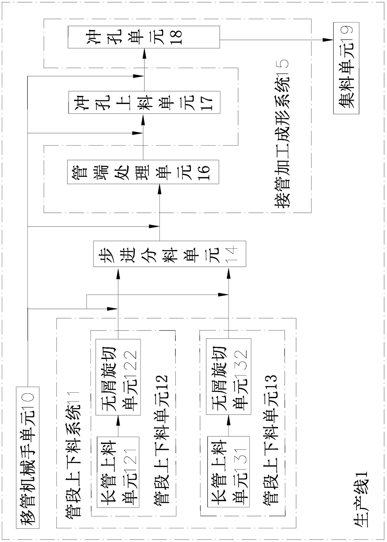
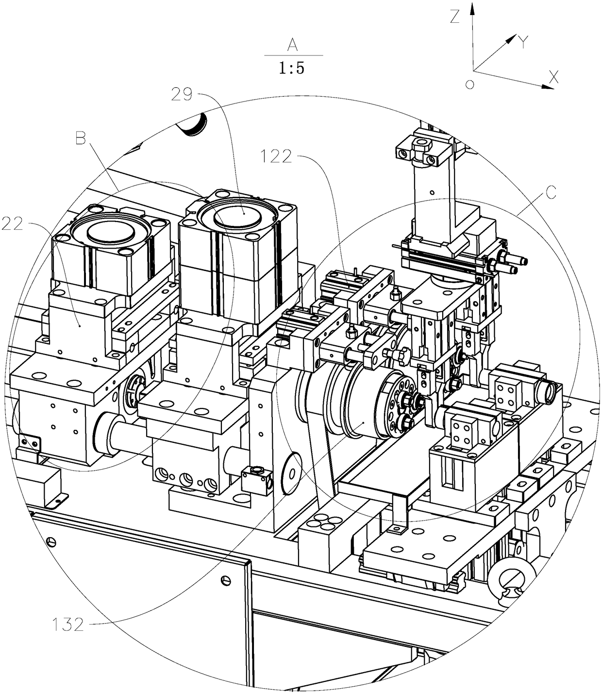
[0035] see Figure 1 to Figure 5 , the production line 1 of the present invention includes a control unit, a frame 100, and a pipe section loading and unloading system 11 installed on the frame 100, a processing and forming system 15, a material transfer system and a collection unit 19, and the material transfer system is used for the pipe section loading and unloading system The short pipe sections cut out in 11 are supplied to the processing and forming system 15 according to a predetermined procedure, and the collecting unit 19 is used to collect the S pipes processed and produced by the processing and forming system 15 . The control unit includes a processor, a memory, and a control panel 101. The control panel 101 is used to receive control instructions input by the operator, and the processor executes the program cor...


PUM


Abstract

The invention relates to a production line for manufacturing an S connecting pipe, and belongs to the technical field of pipe processing and processing. The production line comprises a machine frame,a feeding and discharging system and a connecting pipe machining forming system, the feeding and discharging system and the connecting pipe machining forming system are arranged on the machine frame;the feeding and discharging system comprises more than two pipe section feeding and discharging units which are arranged side by side; the pipe section feeding and discharging units comprises long pipe feeding units, and chip-free rotary cutting units are used for cutting the feeding long pipe material into pipe sections; the machining forming system comprises a pipe end processing unit for performing pipe end processing on at least one end part of the pipe sections, and a punching unit is used for punching the pipe sections treated by the pipe ends; a material shifting system is installed onthe machine frame, pipe sections which are cut by two or more pipe section feeding and discharging units arranged side by side are alternately transferred to the pipe end processing unit, and transferring the pipe sections treated by the pipe ends to the pipe end processing unit. The production line is high in automation degree, the production efficiency and flexibility of the production line areeffectively improved, and can be widely applied to the technical field of manufacturing of air conditioners and automobiles.

Description

technical field [0001] The invention relates to a processing and forming equipment for pipe fittings, in particular to a production line for manufacturing S-joints. Background technique [0002] As the main component of refrigeration equipment, the four-way valve is used to control the switching between the thermal cycle and the refrigeration cycle. It has an E connection, an S connection and a C connection. The specific structure is disclosed in patent documents such as the publication number CN101324277A and the announcement number CN201391635Y. The four-way valve, as shown in the attached figure, is connected to the side branch pipe on the S pipe between the E pipe and the C pipe. Therefore, when manufacturing the S pipe, it needs to be punched; in addition, if the bulletin number is The outer end of the S connecting pipe disclosed in the patent document CN201391635Y is a flaring end, so in the manufacturing process, it is necessary to perform pipe end treatments such as ...

Claims


Application Information

Patent Timeline
Patent Type & Authority Applications(China)
IPC IPC(8): B23P23/06
CPCB23P23/06
Inventor 张良段冰黄中龙潘国峰
Owner 浙江长兴和良智能装备有限公司
Learn More