Broken soap recycling device

A soap and cylinder technology, applied in the field of household appliances, can solve the problems of high heating time control, time-consuming and laborious, complicated operation process, etc., achieve the effect of complete pressing process, solve resource waste, and convenient operation

Pending Publication Date: 2019-01-04
XIANGTAN UNIV
View PDF10 Cites 0 Cited by
  • Summary
  • Abstract
  • Description
  • Claims
  • Application Information

AI Technical Summary

Problems solved by technology

For example, the method has high requirements on temperature and heating time control, the operation process is complicated, time-consuming and laborious, and the practicability is not high; neither method 2 nor method 3 can realize the re-pressing of broken soap pieces, and use cloth bags or bottles to hold them. Easy to breed bacteria and cause harm to human health
[0007] For the above problems, there are the following solutions in the technical field: Chinese patent (patent No. 201310361043.8) provides a soap recovery device, including a housing, a blade, and a base, and the housing is divided into an upper cylinder and a lower cylinder. The radius of the bottom circle of the cylinder is smaller than the radius of the lower cylinder; the device cannot quickly compress the crushed soap bar into a large soap bar that is easy to grab and use
The Chinese patent (patent number: 201720073993.4) ​​provides a soap head reuse device, including a container and a bottle cap, the bottom of the container is movable and connected to a control base, and the bottom of the container is provided with a cone-shaped The groove of the round table also has the limitation that it cannot be pressed quickly to obtain a large soap block
[0008] To sum up, there is currently no broken soap recycling device that has simple and compact structure, convenient operation, low cost, clean and hygienic, environmental protection and energy saving, and integrates the functions of crushing and pressing of broken soap pieces

Method used


Image

  • Broken soap recycling device
  • Broken soap recycling device
  • Broken soap recycling device

Examples


Embodiment Construction

[0035] In order to better describe the technical solutions and advantages of the present invention, the technical solutions in the embodiments of the present invention are now clearly and completely described in conjunction with the accompanying drawings.

[0036] like Figure 1 to Figure 8 Shown is the accompanying drawing of the specific embodiment of the present invention.

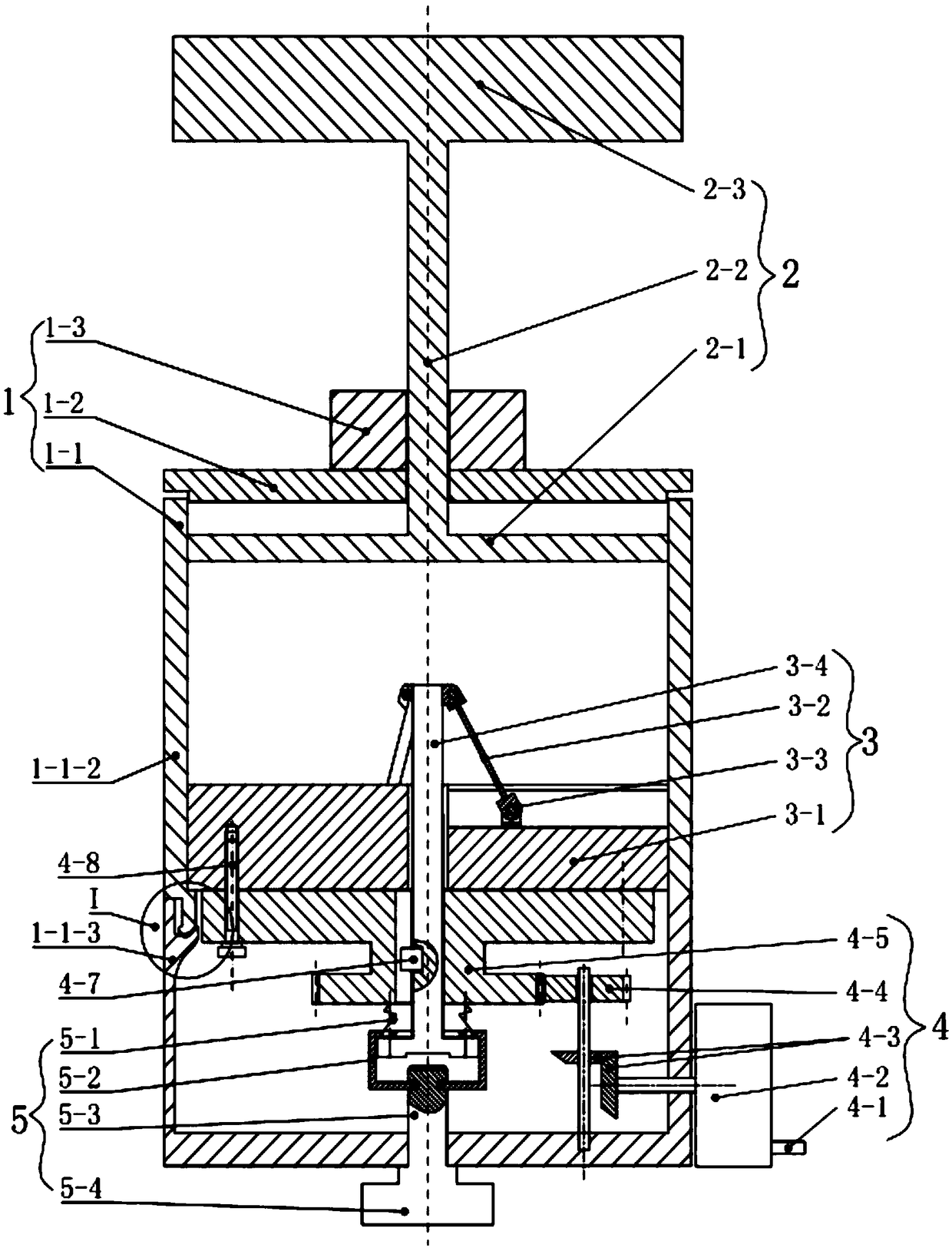
[0037] like Figure 1 to Figure 8 As shown, a crushed soap recycling device includes a bin body 1, a pressing mechanism 2, a cutting mechanism 3, a power mechanism 4, and a push rod reset mechanism 5, and is characterized in that:

[0038] The warehouse body 1 includes a shell cylinder 1-1 and a cylinder end cover 1-2, wherein: the shell cylinder 1-1 adopts a split structure, including an upper cylinder 1-1-2 and a lower cylinder seat 1-1-3 ; The upper cylinder body 1-1-2 and the lower cylinder base 1-1-3 pass as Figure 8 The shown elastic buckle structure (not numbered) is snapped together; the cyl...


PUM


Abstract

A broken soap recycling device comprises a cartridge body, a press forming mechanism, a cutting mechanism, a power mechanism, and an ejector rod resetting mechanism; the cartridge body comprises a housing cylinder and a cylinder end cap, and the cylinder end cap is assembled above the housing cylinder; the press forming mechanism comprises a pressing plate, a pressing rod and a handle, and one endof the pressing rod movably penetrates through the cylinder end cap; the cutting mechanism comprises a cutter head, a cutter, a slider, an ejector rod and a spring, and is arranged in the housing cylinder; the power mechanism comprises a driving wheel, a connecting wheel and a transmission mechanism, and the connecting wheel is coaxially arranged directly below the cutter head; and the ejector rod resetting mechanism comprises a buffer spring, a movable connecting lantern ring, and a resetting push rod. The device is simple and compact in structure, convenient to operate, low in cost, clean and hygienic, environmentally friendly and energy-saving, and integrates the functions of crushing and press-forming broken soap.

Description

technical field [0001] The invention belongs to the field of living utensils, and relates to a crushed soap recycling device, in particular to a household recycling device which integrates crushing and pressing of crushed soap pieces for household use. Background technique [0002] It can be seen from daily life that the soap bar will become smaller and smaller as it is used, and finally soap fragments or flakes will be formed, which brings great inconvenience to continued use. People usually discard these soap crumbs or flakes in order to save washing time, thereby causing waste of resources and environmental pollution. Generally speaking, in order to improve the reuse rate of crushed soap, people often use the following three methods: [0003] 1. Remake crumbled soap into large soap bars. Put the crushed soap together and add water to heat until soft, then pour it into a mold and press it into a soap block; or put the crushed soap block into a small bowl, heat it in a mi...

Claims


Application Information

Patent Timeline
Patent Type & Authority Applications(China)
IPC IPC(8): C11D13/18C11D13/22
CPCC11D13/18C11D13/22
Inventor 张魁刘海成杨长何仕海
Owner XIANGTAN UNIV
Why Eureka
Try Eureka