Cable cutting device and cable-stayed dismantling construction method

A cutting device and cable clamp technology, which is applied in the erection/assembly of bridges, bridge maintenance, bridge reinforcement, etc., can solve problems such as the large impact force of the cables, and achieve the effect of ensuring safety and saving removal time.

Pending Publication Date: 2019-01-04
CHINA MERCHANTS CHONGQING COMM RES & DESIGN INST
View PDF7 Cites 7 Cited by
  • Summary
  • Abstract
  • Description
  • Claims
  • Application Information

AI Technical Summary

Problems solved by technology

[0005] Based on this, it is necessary to provide a cable cutting device and a cable removal construction method for the problem that a very large impact force will be generated when the cable is cut in the traditional cable removal construction method

Method used


Image

  • Cable cutting device and cable-stayed dismantling construction method
  • Cable cutting device and cable-stayed dismantling construction method
  • Cable cutting device and cable-stayed dismantling construction method

Examples


Embodiment Construction

[0030] In order to make the above objects, features and advantages of the present invention more comprehensible, specific implementations of the present invention will be described in detail below in conjunction with the accompanying drawings. In the following description, numerous specific details are set forth in order to provide a thorough understanding of the present invention. However, the present invention can be implemented in many other ways different from those described here, and those skilled in the art can make similar improvements without departing from the connotation of the present invention, so the present invention is not limited by the specific implementations disclosed below.

[0031] It should be noted that when an element is referred to as being “fixed” to another element, it can be directly on the other element or there can also be an intervening element. When an element is referred to as being "connected to" another element, it can be directly connected ...


PUM


Abstract

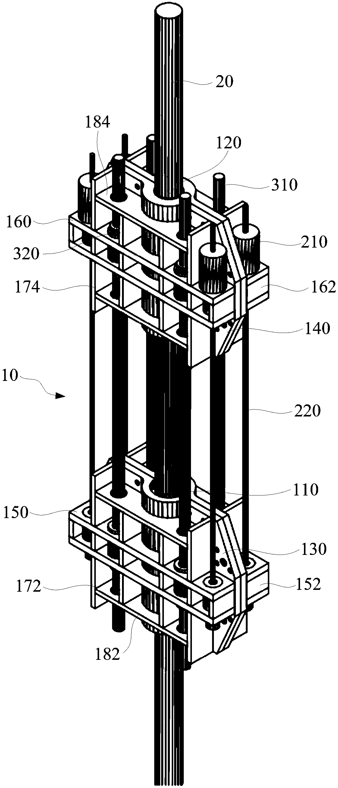
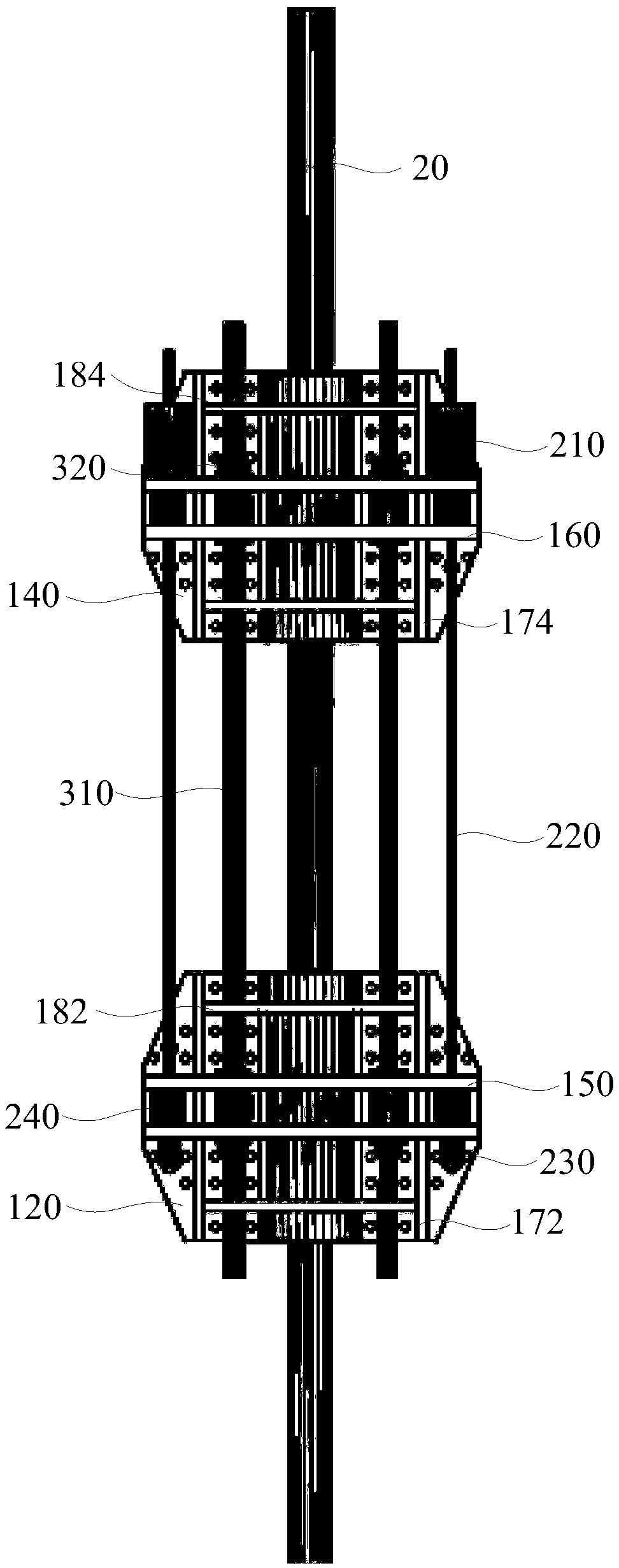
The invention discloses a cable cutting device and a cable dismantling construction method. The first anchor and the second anchor are sleeved on the cable at intervals, and then the first cable is clamped on the first anchor and the second cable is clamped on the second anchor. A steel strand is stretched with a jack to apply a pretension force to the first and second cable clamps while the cablebody is partially unloaded between the cable clamps and the steel strand bears a portion of the cable force. Tighten the retaining nut and loosen the jack to transfer the cable force on the strandedwire to the tie rod. The cable body is cut in stages, in which the cable force decreases gradually and the force on the tie rod increases gradually until the cable is completely cut off. Loosen the retaining nut, remove the cable cutting device and remove the cut cable. By using the device to cut the stay cable, the impact force is not generated when the stay cable is cut, and the adjacent stay cable is not broken, or the main beam is cracked or even broken, so as to ensure the safety and greatly save the removal time of the stay cable.

Description

technical field [0001] The invention relates to the technical field of cable load-bearing bridge drag (hanging) cable replacement, in particular to a drag cable cutting device and a drag cable removal construction method. Background technique [0002] The cable-stayed bridges, suspension bridges or mid-under-supported arch bridges built in my country in the early days had a long operating time, and due to design, construction or post-maintenance reasons, the anchor rings of the upper and lower anchor heads were damaged due to corrosion or excessive processing and matching accuracy errors. The anchor ring cannot be withdrawn, or the cable anchor pipe anchored on the concrete main beam is filled with pebble concrete or epoxy mortar, making it difficult for the upper and lower anchor heads to withdraw normally according to conventional methods. [0003] If the cable is cut directly without protection, a very large impact force will be generated when the cable is cut, which may c...

Claims


Application Information

Patent Timeline
Patent Type & Authority Applications(China)
IPC IPC(8): E01D22/00
CPCE01D22/00
Inventor 严琨李琦吴尚东蒋超越温晓明郁泽华刘宁国陈育廷毛振方王明洋
Owner CHINA MERCHANTS CHONGQING COMM RES & DESIGN INST
Why Eureka
Try Eureka