
Hydrostatic slide device

A technology of hydrostatic pressure and slider, which is applied in the direction of hydrostatic bearings, liquid cushion bearings, bearings, etc., and can solve the problem of inability to adjust the oil pressure and maneuverability

Inactive Publication Date: 2019-01-04
PROTH INDAL
View PDF8 Cites 0 Cited by
  • Summary
  • Abstract
  • Description
  • Claims
  • Application Information

AI Technical Summary

Problems solved by technology

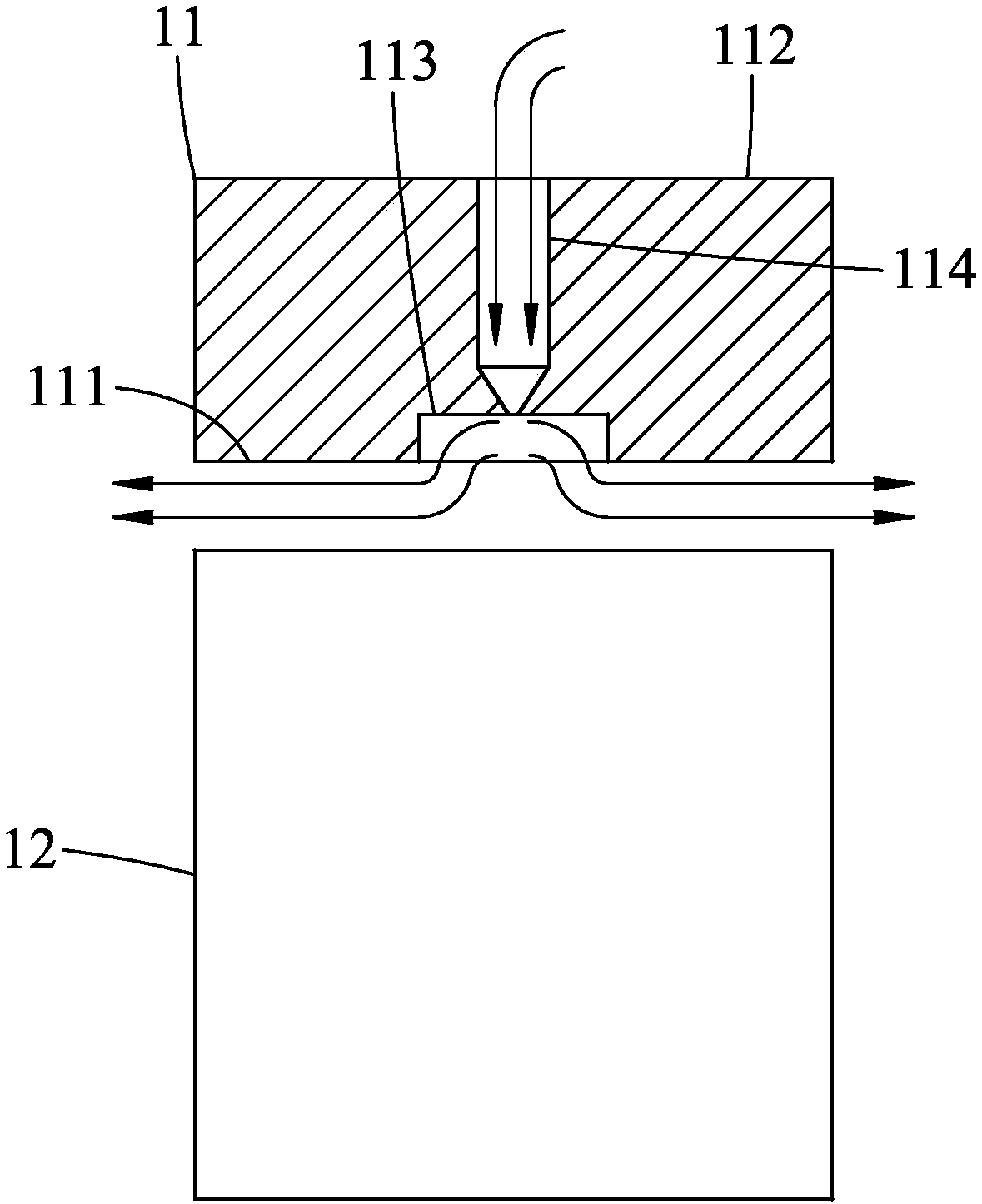
However, the existing restrictor (not shown in the figure) can only maintain a constant throttling amount according to the setting, so the oil pressure in the oil chamber 113 cannot be adjusted flexibly

Method used


Image

  • Hydrostatic slide device
  • Hydrostatic slide device
  • Hydrostatic slide device

Examples


Embodiment Construction

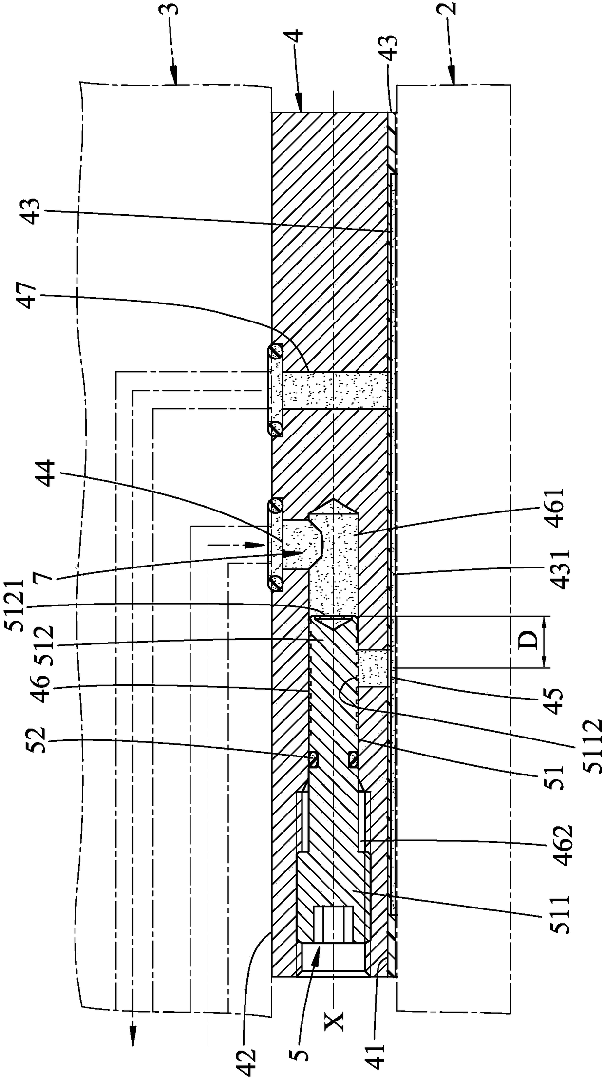
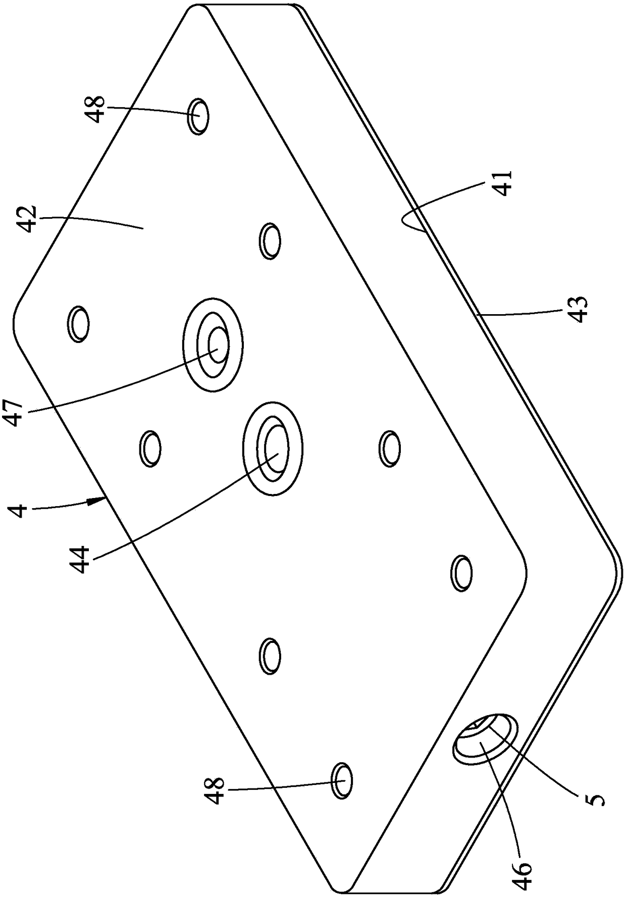
[0024] refer to figure 2 , image 3 and Figure 4 , an embodiment of the hydrostatic slider device of the present invention, slides on a slide rail 2 and carries a workbench 3 . The hydrostatic slider device includes a slider 4 and a capillary restrictor 5 .

[0025] The slider 4 includes a sliding surface 41 facing the slide rail 2, an engaging surface 42 opposite to the sliding surface 41 and facing the workbench 3, and a wear-resistant surface formed on the sliding surface 41. Layer 43, an inlet 44 formed on the joint surface 42 and used to introduce the lubricating fluid 7, an outlet 45 formed on the sliding surface 41 and used to release the lubricating fluid 7, a throttle hole 46, a pressure A detection hole 47 , and a plurality of locking holes 48 extending from the joint surface 42 toward the sliding surface 41 .

[0026] The wear-resistant layer 43 is a polymer resin material with a friction coefficient less than 0.2, with a thickness of about 2-4 mm, and has a c...


PUM


Abstract

A hydrostatic slide device that slides over a slide rail includes a slider and a capillary flow regulator that can be adjusted. The slider includes a sliding surface facing the sliding rail, a wear-resistant layer formed on the sliding surface and defining a chamber, a throttling orifice communicating with the chamber, and a pressure detecting passage connecting the chamber. The wear-resistant layer is an epoxy resin coating material. The capillary flow regulator and the throttling orifice are threaded to adjust the capillary length, and cooperate with the pressure detecting passage to obtainsuitable throttling parameters. Thereby, in the case that lubricating fluid supply is insufficient, the wear-resistant layer is in contact with the sliding rail to avoid the rail damage, and the service life of the static pressure bearing group is greatly prolonged. When damage of the wear-resistant layer is not serious, the capillary flow regulator can be directly adjusted to control the hydraulic pressure in the chamber, so that the load of the slider can be stabilized.

Description

technical field [0001] The invention relates to a slider, in particular to a hydrostatic slider device. Background technique [0002] refer to figure 1 , a conventional hydrostatic slider 11 sliding on a slide rail 12 . The slider 11 includes a sliding surface 111 facing the slide rail 12, a joint surface 112 opposite to the sliding surface 111 and connected to a workbench (not shown in the figure), and formed on the sliding surface 111. An oil cavity 113, and a flow channel 114 formed on the joint surface 112 and communicated with the oil cavity 113 for introducing lubricating oil. Thereby, lubricating oil injected under high pressure will be filled between the slide rail 12 and the slider 11 from the oil chamber 113 to form an oil film, so that the aforementioned workbench and the slider 11 can pass through the aforementioned flowing oil film Float, and can make linear displacement along the slide rail 12 smoothly under the condition of no friction. [0003] However, i...

Claims


Application Information

Patent Timeline
Patent Type & Authority Applications(China)
IPC IPC(8): F16C32/06F16C33/20
CPCF16C32/0629F16C32/0666F16C32/067F16C32/0688F16C33/20
Inventor 张育正
Owner PROTH INDAL
Learn More