Movable heat storage container and heat release method thereof

A container and mobile technology, applied in the application field of solar energy technology, can solve the problems of limited space, difficult design, low efficiency, etc., and achieve the effects of reduced transportation costs, stable heat supply, and low metering costs

Inactive Publication Date: 2019-01-04
SOUTHEAST UNIV
View PDF5 Cites 1 Cited by
  • Summary
  • Abstract
  • Description
  • Claims
  • Application Information

AI Technical Summary

Problems solved by technology

[0003] The technical problem to be solved by the present invention is to provide a movable heat storage container and its charging and discharging method, which can separate the production, stora

Method used


Image

  • Movable heat storage container and heat release method thereof
  • Movable heat storage container and heat release method thereof
  • Movable heat storage container and heat release method thereof

Examples


Embodiment Construction

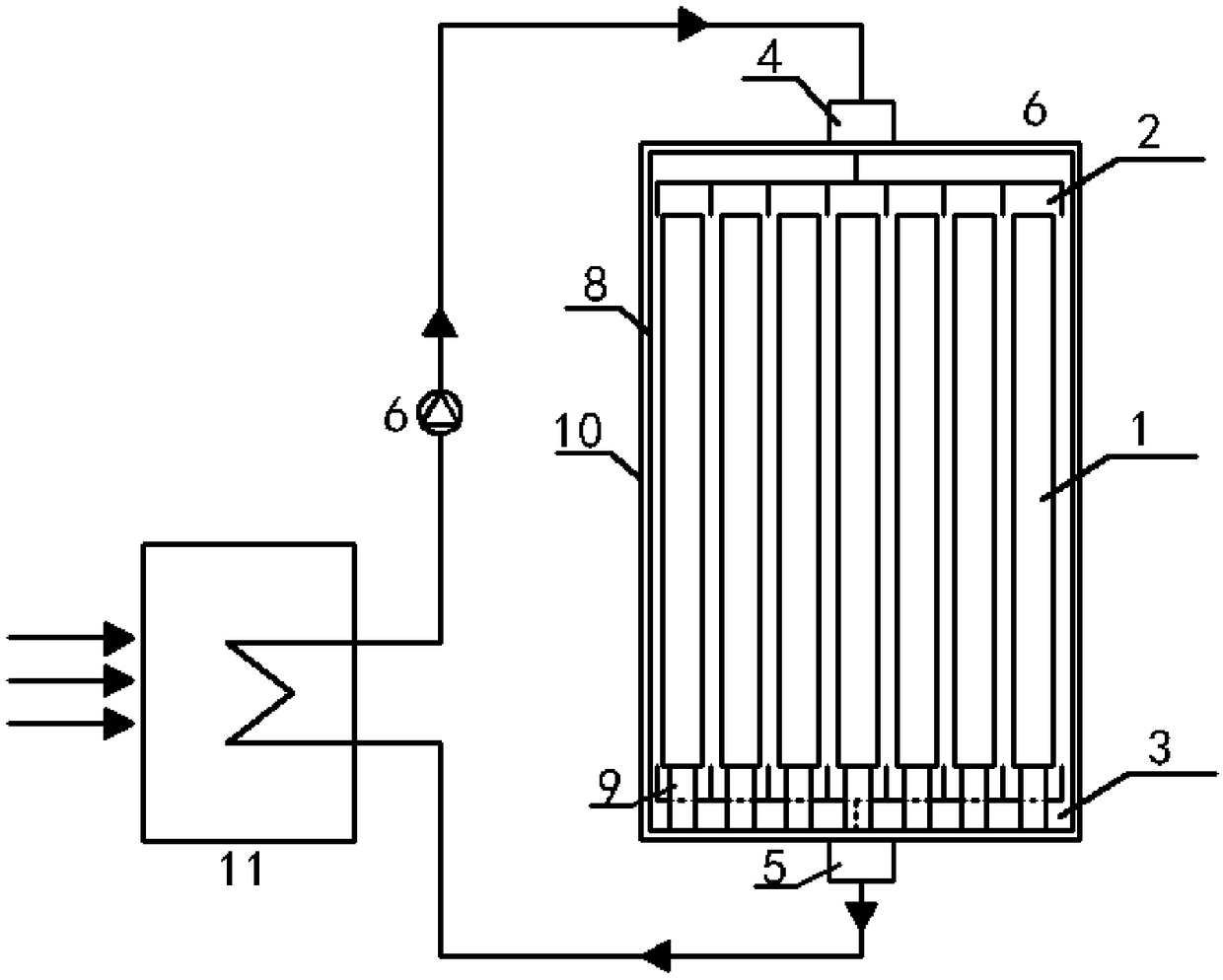
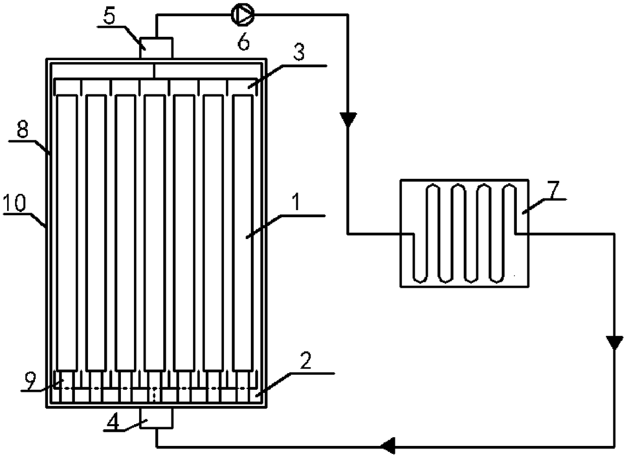
[0022] Such as Figure 1-4 As shown, a movable heat storage container includes: multiple heat storage rods 1, heat transfer oil diverter 2, heat transfer oil collector 3, heat transfer oil inlet 4, heat transfer oil outlet 5, oil pump 6, heat release Heat exchanger 7, box body 8, metal keel 9, thermal insulation material 10 and oil tank 11; multiple heat storage rods 1 are arranged in box body 8 according to rules; heat transfer oil inlet 4 and heat transfer oil outlet 5 are located at the bottom of box body 8 Above and below; the heat transfer oil inlet 4 and the heat transfer oil outlet 5 are connected with the heat transfer oil diverter 2 and the heat transfer oil collector 3, and the flow direction of the heat transfer oil is longitudinal, from top to bottom or from bottom to top; the metal keel 9 swings It is placed directly under the heat storage rod 1; the box body 8 is wrapped with an insulating material 10. The oil pump 6 is connected to the heat transfer oil inlet 4...


PUM

PropertyMeasurementUnit
Inscribed circle diameteraaaaaaaaaa

Abstract

The invention discloses a movable heat storage container and a heat release method thereof. The container comprises a plurality of heat storage rods, heat conduction oil splitters and heat conductionoil current collectors, a heat conduction oil inlet, a heat conduction oil outlet, an oil pump, a heat release heat exchanger, a box body, metal keels, a heat insulation material and an oil tank; theheat release method comprises a heat charging process, a transportation process and a heat release process. According to the movable heat storage container and the heat release method, renewable energy sources are produced, stored and used separately, the problems that a traditional renewable energy supply system is difficult to design, high in cost, low in efficiency and limited in use site are effectively solved.

Description

technical field [0001] The invention relates to the application field of solar energy technology, in particular to a movable heat storage container and a heat charging and discharging method thereof. Background technique [0002] The current renewable energy supply method is to establish a renewable energy system at a designated site, and the system uses local wind energy, solar energy, biomass energy or other forms of energy to provide ideal energy such as heat energy, but this type of renewable energy system exists. The following problems: (1) The end users have different requirements for the medium and grade of the terminal heat energy, which brings difficulties to the system design; (2) The place where the conditional construction of the renewable energy system and the place where the energy is used need more efficient However, traditional hot water energy storage solutions are not easy to store high-grade heat energy, and there are still problems such as low heat storag...

Claims


Application Information

Patent Timeline
IPC IPC(8): F24S60/00F24S80/00
CPCY02E10/40
Inventor 匡荛郭昕刘光鹏王凯丽袁瑀浩
Owner SOUTHEAST UNIV
Why Eureka
Try Eureka