Displacement sensor with refractor and capable of improving magnification times and measurement method thereof

A displacement sensor and magnification technology, which is applied in the field of measurement, can solve the problems such as the sensor magnification is easily affected and the measurement accuracy drops, and achieves the effects of continuous displacement measurement, improving measurement accuracy, and solving the limitation of magnification

Pending Publication Date: 2019-01-04
BEIFANG UNIV OF NATITIES
View PDF7 Cites 2 Cited by
  • Summary
  • Abstract
  • Description
  • Claims
  • Application Information

AI Technical Summary

Problems solved by technology

However, for the displacement sensor in the prior art, for example, the application number is 201810736602.1, and the title of the invention is the displacement sensor provided in "Displacement Sensor and Its Measurement Method That Can Increase Magnification". The displacement measurement principle and structure are as follows: Figure 7 As shown, the measurement magnification of the displacement sensor is related to the incident angle of the PSD, and the magnification of the sensor is easily affected, that is, when the incident angle of the laser beam incident on the PSD increases, the measurement accuracy of the PSD itself will decrease.

Method used


Image

  • Displacement sensor with refractor and capable of improving magnification times and measurement method thereof
  • Displacement sensor with refractor and capable of improving magnification times and measurement method thereof
  • Displacement sensor with refractor and capable of improving magnification times and measurement method thereof

Examples


Embodiment 1

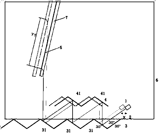
[0046] see figure 1 In this embodiment, a displacement sensor with a refracting mirror that can increase the magnification is provided, including a laser source 1, a laser beam 2, a triangular wave reflector 3, and the triangular wave reflector 3 includes a reflective surface 31, and a reflector group 4 , The reflector group 4 includes a reflector 41 , a photodetector 5 , a casing 6 , and a refractor 7 .

[0047] In this new type of displacement sensor with a refracting mirror that can increase the magnification:

[0048]The laser source 1 emits the laser beam 2, and makes the laser beam 2 shoot to the first reflective surface 31 of the triangular wave reflector 3; the first reflector 41 of the mirror group 4 corresponding to the first reflective surface 31 is used to receive The laser beam 2 is reflected by the first reflective surface 31 of the triangular wave reflector 3, and the laser beam is reflected to the triangular wave reflector along the same path during the measu...

Embodiment 2

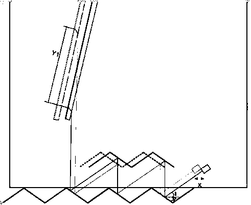
[0068] can refer to Figure 4 ,Such as Figure 4 As shown, compared with the displacement sensor with a refracting mirror that can increase the magnification in this embodiment and the displacement sensor that can increase the magnification with a refracting mirror described in Embodiment 1, the difference is that in this embodiment The multiple reflectors are directly connected to form an inline structure as a whole.

Embodiment 3

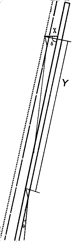
[0070] can refer to Figure 5 Compared with the displacement sensor with a refracting mirror that can increase the magnification in this embodiment and the displacement sensor that can increase the magnification with a refracting mirror described in Embodiment 2, the difference is that: provided in this embodiment The displacement sensor with a refracting mirror that can increase the magnification includes two reading heads, and the two reading heads have the same structure and are placed symmetrically.


PUM


Abstract

The present invention provides a displacement sensor with refractor and capable of improving magnification times and a measurement method thereof. The displacement sensor comprises: a laser source configured to emit a laser beam, wherein the laser beam is incident into a reflection surface of a triangular wave reflector; a reflector set comprising at least two reflectors, wherein the reflectors are configured to receive laser beams reflected corresponding to the reflection surfaces and allow the received laser beams to be reflected again; the reflection surfaces configured to allow the laser beams emitted by the laser source or the laser beams reflected by the reflector to be reflected again; a refractor configured to receive the laser beams which are reflected by the reflection surfaces,do not received by the reflector set any longer and allow the laser beams to generate refraction; and a photoelectric detector configured to receive the laser beams refracted by the refractor and measure the incident positions of the laser beams. Through arrangement of the refractor, the angle of the laser incident to the photoelectric detector is reduced, and the displacement sensor can further improve the displacement measurement precision.

Description

technical field [0001] The invention relates to the field of measurement technology, in particular to a displacement sensor with a refracting mirror that can increase the magnification and a measurement method thereof. Background technique [0002] The new principle of displacement measurement based on the optical triangular amplification method is realized on the basis of the optical triangular amplification method, combined with triangular wave optical devices and high-precision PSD (Position Sensitive Device, position sensitive (sensitive) detector). The triangular wave optical device subdivides the linear displacement into equal intervals, reduces the processing accuracy and size requirements of optical devices, and at the same time reduces the size requirements of high-precision PSD, and realizes high-precision displacement measurement in a small range. The principle of displacement measurement based on the optical triangular amplification method is that after the relat...

Claims


Application Information

Patent Timeline
Patent Type & Authority Applications(China)
IPC IPC(8): G01B11/02
CPCG01B11/026
Inventor 张白张家坤杨海涛
Owner BEIFANG UNIV OF NATITIES
Why Eureka
Try Eureka