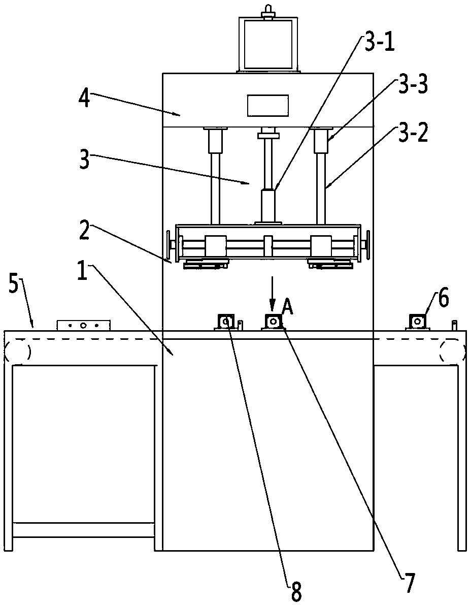
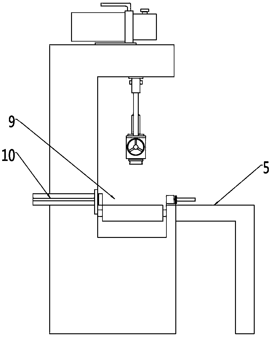
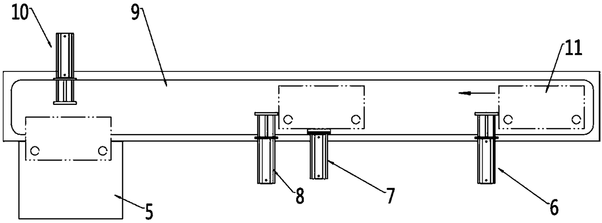
Storage battery airtightness detection and inflation method and equipment

A technology for air tightness detection and inflatable equipment, which is applied in liquid tightness measurement using liquid/vacuum degree, battery machine assembly, climate sustainability, etc. Insufficient and other issues

Pending Publication Date: 2019-01-04
FENGFAN
View PDF0 Cites 13 Cited by
  • Summary
  • Abstract
  • Description
  • Claims
  • Application Information

AI Technical Summary

Problems solved by technology

This traditional detection method has the following problems: 1. After the battery is inflated, the side of the battery tank will be convex and deformed, which will affect the bonding effect of the battery tank cover and cause battery leakage in severe cases; After the battery with protective gas is inflated and

Method used


Image

  • Storage battery airtightness detection and inflation method and equipment
  • Storage battery airtightness detection and inflation method and equipment
  • Storage battery airtightness detection and inflation method and equipment

Examples


Embodiment 1

[0034] Embodiment 1: The model of the battery to be tested is 6QW-60, and the battery to be tested is transported to the detection position by the battery delivery track of the equipment described in the present invention, and the air cylinder on both sides of the battery is closed by clamping the cylinder, the vacuum air pipe is opened, and the protective gas The trachea is closed, and the vacuum pump pumps vacuum into the battery; the vacuuming time is 15 seconds, and the internal pressure of the battery is 3KPa, so it is judged that the sealing of the battery is unqualified.

Embodiment 2

[0035] Embodiment 2: The model of the battery to be tested is 6QW-80, and the battery to be tested is transported to the detection position by the battery delivery track of the equipment described in the present invention, and the air cylinder on both sides of the battery is closed by clamping the cylinder, the vacuum air pipe is opened, and the protective gas The trachea is closed, and the vacuum pump pumps vacuum into the battery; the vacuuming time is 10 seconds, the internal pressure of the battery is -26KPa, and the internal pressure of the battery is -25.9Kpa after holding the pressure for 8 seconds. The gas gas pipe is connected and opened, and the protective gas carbon dioxide is charged into the battery, and the inflation time is 5-8s, and the internal pressure of the battery is charged to 8Kpa.

Embodiment 3

[0036] Embodiment 3: The model of the battery to be tested is 6QW-100, and the battery to be tested is transported to the detection position by the battery delivery track of the equipment described in the present invention. The trachea is closed, and the vacuum pump pumps vacuum into the battery; the vacuuming time is 9 seconds, the internal pressure of the battery is -23KPa, and the internal pressure of the battery is -22.7Kpa after holding the pressure for 9 seconds. The gas gas pipe is connected and opened, and the protective gas carbon dioxide is charged into the battery, and the inflation time is 5-8s, and the internal pressure of the battery is charged to 10Kpa.


PUM


Abstract

The invention provides a storage battery airtightness detection and inflation method comprising the following steps: a, sealing the detected storage battery vent hole and vacuumizing the storage battery by a vacuum pump; b, maintaining the negative pressure state in the storage battery; c, judging whether the storage battery airtightness is qualified according to the time when the vacuum degree ofthe storage battery reaches the negative pressure requirement and the negative pressure change value in the storage battery after the end of pressure maintaining; and d, removing the defective storage batteries detected in the step c and piping the protective gas into the qualified storage batteries. The conventional method of using positive pressure inflation to detect the airtightness is changed into using negative pressure pumping to detect the airtightness so that convex deformation of the side wall of the storage battery tank caused by inflation can be effectively avoided; the protectivegas is piped into the qualified storage batteries at the detection position after detecting the airtightness by the negative pressure so that the deflation link can be reduced and the work efficiencycan be enhanced and the piping quality of the protective gas can be enhanced. The labor cost can be saved, the production efficiency can be enhanced and the inflation quality consistency can be guaranteed.

Description

technical field [0001] The invention relates to a storage battery air tightness detection, charging method and equipment, belonging to the technical field of storage batteries. Background technique [0002] With the rapid development of the automobile industry, the sales of lead-acid batteries are increasing year by year, more and more consumers are using lead-acid battery products, and lead-acid batteries are being used more and more in non-vehicle fields such as lighting and power supply. Lead-acid batteries mostly use plastic tanks and covers. During the production process, the tanks and covers are bonded together by hot melting. Is it good. The traditional air-tightness detection method is to detect the leakage of the air pressure within a certain holding time by sealing the battery exhaust hole to inflate the inside of the battery. This traditional detection method has the following problems: 1. After the battery is inflated, the side of the battery tank will be conve...

Claims


Application Information

Patent Timeline
IPC IPC(8): G01M3/26H01M10/04
CPCH01M10/0404G01M3/26Y02P70/50
Inventor 黄涛霍永旺刘海王廷华王静柳辉王丽娟
Owner FENGFAN
Why Eureka
Try Eureka