
Wave simulation generating device under high gravity field

A technology for generating devices and supergravity fields, applied in measuring devices, fluid dynamics tests, testing of machine/structural components, etc., can solve problems such as deformation of force transmission structures, long force transmission paths, and complex structural forms, and achieve institutional The effect of small jamming, small load and simple structure

Active Publication Date: 2019-01-04
GENERAL ENG RES INST CHINA ACAD OF ENG PHYSICS
View PDF10 Cites 15 Cited by
  • Summary
  • Abstract
  • Description
  • Claims
  • Application Information

AI Technical Summary

Problems solved by technology

The current rocking plate wave-making is driven by a motor, the force is transmitted by the cam and the connecting rod, and the sliding mechanism realizes the structural form of motion decoupling. , the force transmission structure is prone to deformation, resulting in the phenomenon of mechanism stuck

Method used


Image

  • Wave simulation generating device under high gravity field
  • Wave simulation generating device under high gravity field
  • Wave simulation generating device under high gravity field

Examples


Embodiment 1

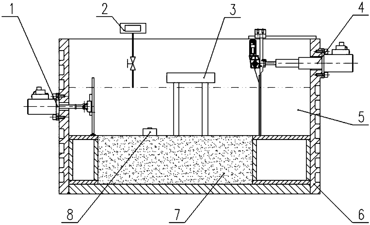
[0051] Example 1, such as figure 1 Shown:

[0052]The wave simulation generating device under the supergravity field is installed in the centrifuge basket, and the wave simulation generating device includes:

[0053] A model box 6; a soil body 7 is set at the bottom of the model box 6, a simulated marine structure 3 is set on the soil body 7, and water 5 is placed on the upper part of the soil body 7 in the model box 6;

[0054] A water level control unit 2 for controlling the water level of the water body in the model box 6;

[0055] A wave-making unit 1 for making waves in the direction where the simulated offshore structure 3 is located;

[0056] The wave simulation generator also includes:

[0057] The wave absorbing unit 4 is used for correspondingly absorbing waves of different waveforms generated by the wave making unit 1 .

[0058] The adoption of the wave-absorbing unit 4 can enhance the wave-absorbing effect, reduce the influence of reflected waves on the wavefor...

Embodiment 2

[0060] Example 2, such as figure 1 , Figure 5 , Figure 6 as shown,

[0061] The difference between this embodiment and Embodiment 1 is that the simulated offshore structure 3 is arranged between the wave-making unit 1 and the wave-absorbing unit 4, and the wave-absorbing unit 4 includes:

[0062] The wave-absorbing plate 42; the plate surface of the wave-absorbing plate 42 is provided with a plurality of through holes evenly spaced and vertically arranged,

[0063] The first guide rail slider assembly 43; including a guide rail and a slide block, the guide rail is installed on the top of the model box 6, the slide block is slidably installed on the guide rail, the upper end of the wave absorbing plate 42 is fixedly connected with the slide block, and the movement of the wave absorbing plate 42 The direction is a direction towards or away from the wave-making unit 1;

[0064] The wave-absorbing plate moving structure 44; the wave-absorbing plate moving structure 44 is a p...

Embodiment 3

[0070] Example 3, such as Figure 5 as shown,

[0071] The difference between this embodiment and Embodiment 2 is that the moving structure 44 of the wave-absorbing plate is a multi-stage telescopic hydraulic cylinder.

[0072] The movement of the wave absorbing plate 42 with a large stroke can be realized in a small installation space through the multi-stage telescopic hydraulic cylinder.

[0073] The moving structure 44 of the wave absorbing plate also includes high-frequency servo valves and other components. During the specific use process, it is connected with the oil source on the ground through the rotary joint to realize the stable output of the power of the hydraulic cylinder.


PUM


Abstract

The invention discloses a wave simulation generating device under a high gravity field. The adoption of a wave absorbing unit can enhance the wave absorbing effect, reduce the influence of a reflectedwave on a waveform, and ensure the similarity of a wave simulation experiment to real environment simulation. The wave absorbing unit can adjust the position of a wave absorbing plate and the size ofa grating opening according to the waveform generated by a wave generating unit so as to ensure an optimal wave absorbing effect. The wave generating unit realizes force transfer and the decoupling of motion in a simple structure. Compared with a transmission structure with a long transmission path and a complicated structure, the wave simulation generating device is less affected by mechanism jamming caused by deformation of a centrifugal field and ensures the rigidity and stability of a transmission mechanism more easily. Different from a conventional way of moving a push plate as a whole,only the upper part of the push plate is pushed, and so the load on the push plate is small and required power is small. The wave simulation generating device under a high gravity field is suitable for simulation of waves with high water depth and large amplitude.

Description

technical field [0001] The invention belongs to the technical field of wave simulation generation, and in particular relates to a wave simulation generation device under a supergravity field. Background technique [0002] In the environment of supergravity field, the wave simulation generating device generates waves with different wave heights and different durations based on the scaling effect, which provides a simulation test platform for revealing and studying the damage process and mechanism of marine engineering disasters caused by waves on marine structures, and also Provide a verification platform for marine engineering structure and pipeline design methods such as marine resource development platforms. [0003] A few scientific research institutions at home and abroad have built wave simulation devices in the environment of supergravity field, such as the push plate wave simulation device of the Hong Kong University of Science and Technology, the shaking plate wave s...

Claims


Application Information

Patent Timeline
Patent Type & Authority Applications(China)
IPC IPC(8): G01M10/00
CPCG01M10/00
Inventor 李心耀王鑫磊黎启胜宋琼李明海尹鹏
Owner GENERAL ENG RES INST CHINA ACAD OF ENG PHYSICS
Learn More