Shear device and method for detecting magnetic pulse welding connector performance
A technology for welding joints and shearing devices, which is applied to measuring devices and uses a stable shear force to test the strength and strength characteristics of materials, can solve problems such as the strength distribution of the connection area that cannot meet the detection of welding joints, and achieve high efficiency and speed. Effectiveness of testing, simple operation, wide versatility
- Summary
- Abstract
- Description
- Claims
- Application Information
AI Technical Summary
Problems solved by technology
Method used
Image

Examples
Embodiment 1
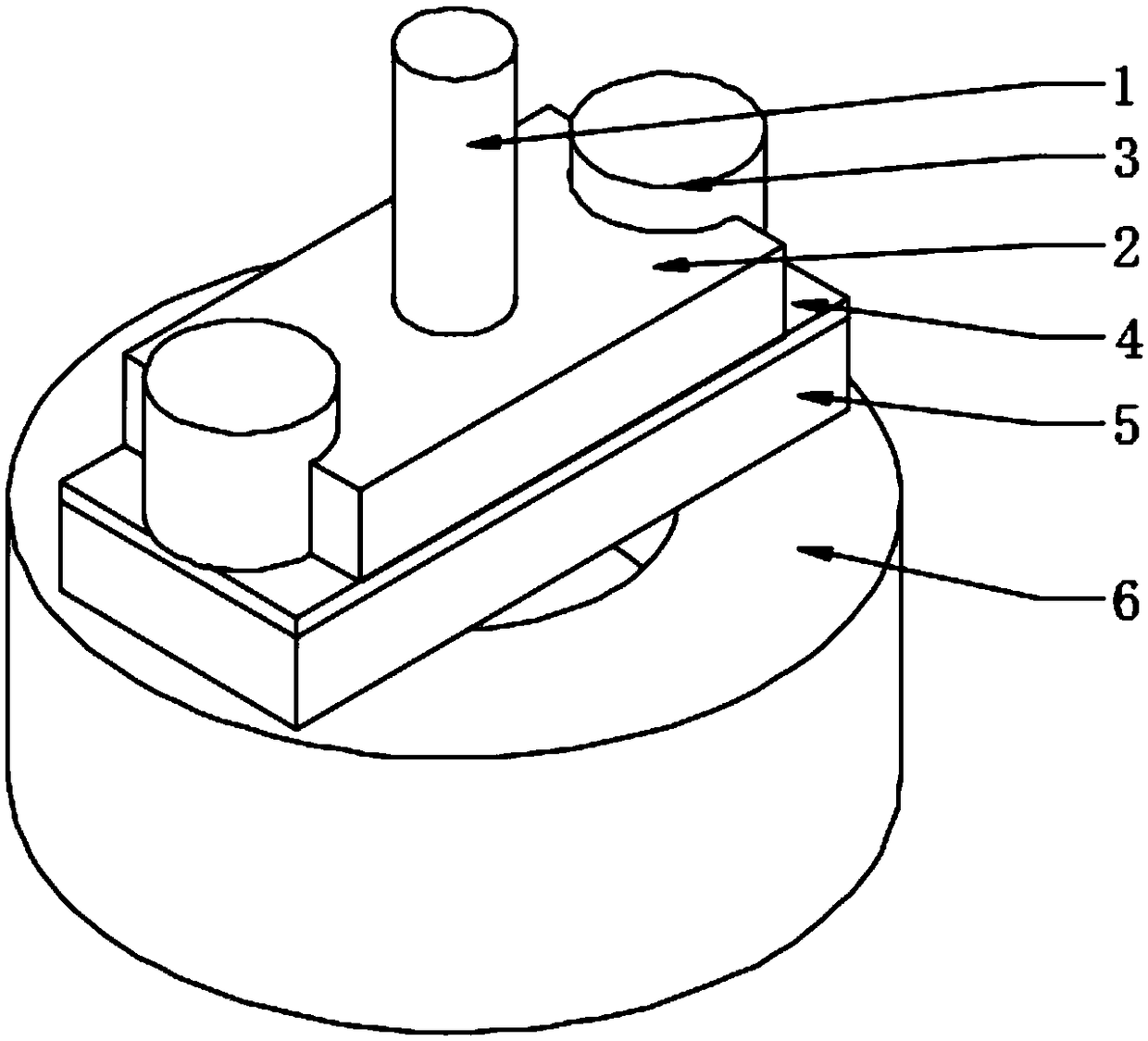
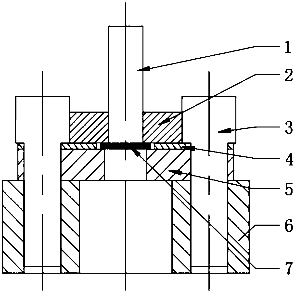
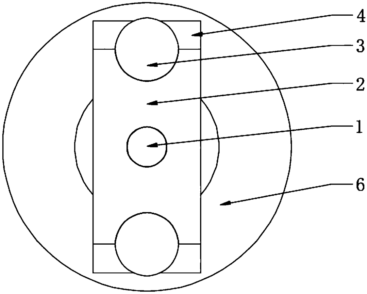
[0035] A specific embodiment of the present invention, such as Figure 1 to Figure 3 As shown, a shearing device for testing the performance of magnetic pulse welded joints is disclosed, including a pressure rod 1, a sample positioning piece 4, a pressure block 5 and a base 6; the base 6 is used to fix the entire shearing device, and the base 6. The pressure receiving block 5 and the sample positioning piece 4 are arranged sequentially from bottom to top, that is, the pressure receiving block 5 is located above the base 6, and the sample positioning piece 4 is located above the pressure receiving block 5; the pressure receiving block 5 is provided with a first aperture The first through hole, the sample positioning piece 4 is provided with a second through hole with a second aperture, the first aperture is smaller than the second aperture, the first through hole and the second through hole are concentrically arranged; the first aperture is larger than that of the inner pipe mem...
Embodiment 2
[0045] Another specific embodiment of the present invention discloses a method for detecting the performance of magnetic pulse welded joints, specifically using the shearing device used for detecting the performance of magnetic pulse welded joints in Embodiment 1 to detect the performance of magnetic pulse welded joints , including the following steps:
[0046] Step 1: Before the shear test, fix the compression block 5 and the sample positioning piece 4 on the base 6, and the sample positioning piece 4 is located between the base 6 and the compression block 5;
[0047] Step 2: Place the welded sample slice 7 in the second through hole of the sample positioning piece 4, place the outer pipe 9 of the welded sample slice 7 on the annular shearing part, and use other methods such as fixing bolts 3 or buckles Fix the positioning block 2, the number of fixing bolts 3 is at least two, and they are arranged symmetrically; the pressure rod 1 is pressed against the inner pipe piece 8 of...
PUM
 Abstract
Description
Claims
Application Information
PatSnap Eureka turns technology decisions into work you can execute. Powered by our Innovation Knowledge Graph, it runs expert workflows across engineering, life sciences, materials and intellectual property. Get your review-ready output in minutes.


