Check patentability & draft patents in minutes with Patsnap Eureka AI!

A dual-range current sensor for new energy vehicles

A current sensor and new energy vehicle technology, which is applied in the direction of changing the range circuit, measuring current/voltage, and only measuring current, etc., can solve the problems of measurement deviation from the set value, decrease of measurement accuracy, and heavy overall weight, etc., to achieve accuracy improvement , Reliability improvement, size reduction effect

Active Publication Date: 2021-08-24
NINGBO CRRC TIMES TRANSDUCER TECH CO LTD
View PDF12 Cites 0 Cited by
  • Summary
  • Abstract
  • Description
  • Claims
  • Application Information

AI Technical Summary

Problems solved by technology

[0008] The overall packaging of the product and the positioning of components are carried out by glue filling. The overall weight is heavy. In order to meet the requirements of glue filling, an additional glue flow channel needs to be designed, resulting in a large product size. Debugging and other work need to be fully positioned after glue filling. after
The glue takes a long time to dry, which is not conducive to automated mass production
Its production is cumbersome, there are many assembly relationships, and the product reliability is poor, which will make the debugging of the product difficult and the pass rate low
In order to increase the mechanical strength, the overall glue is usually used between the various parts, but due to the effect of thermal stress, the air gap of the iron core may change, making the measurement deviate from the set value
[0009] The output of the sensor is directly proportional to the length of the air gap of the iron core. The air gap of the iron core is affected by vibration, impact, drop, glue stress and temperature changes, etc., resulting in slight changes in the air gap, which directly leads to a decrease in measurement accuracy.

Method used


Image

  • A dual-range current sensor for new energy vehicles
  • A dual-range current sensor for new energy vehicles
  • A dual-range current sensor for new energy vehicles

Examples


Embodiment Construction

[0045] Below in conjunction with the accompanying drawings, embodiments of the present invention is further described.

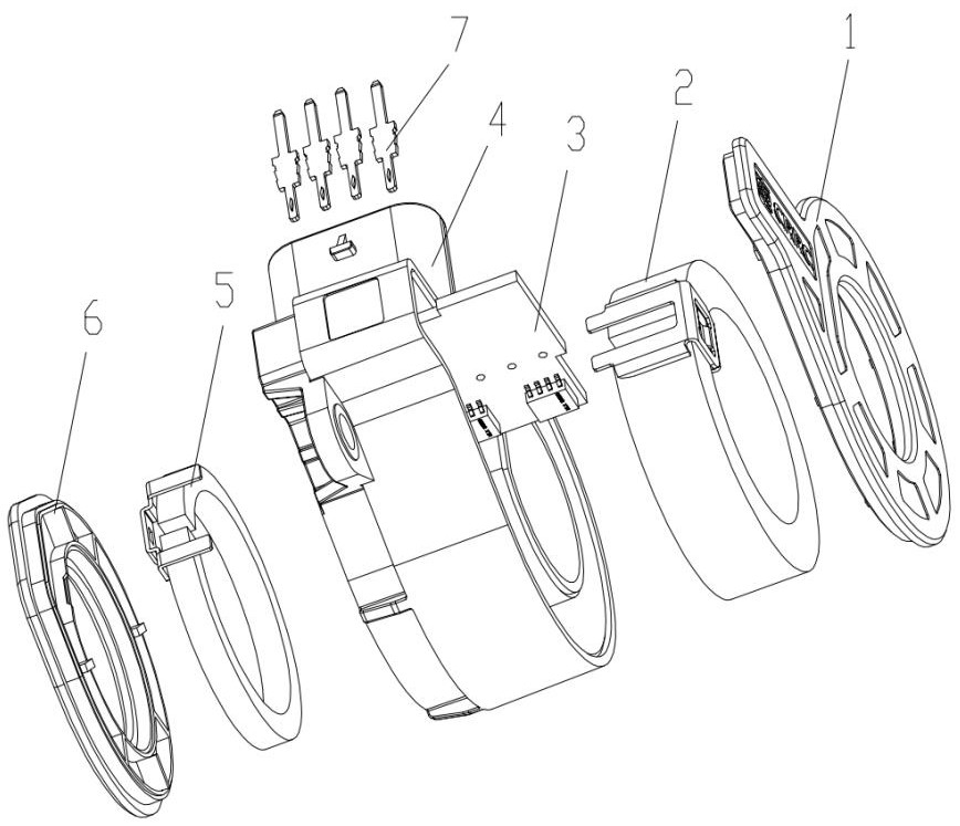
[0046] like Figure 1 Shown, a new energy automotive dual range current sensor, comprising a housing cover 1, a core assembly 2, comprising a Hall ASIC PCB assembly 3, a housing 4, two core assembly 5, two housing cover 6, 7 pin.

[0047] like figure 2 As shown in the core assembly 2 comprises a core 21, the core holder 22, the core holder 22 is fixed to core 21.

[0048] Of the iron core holder 22 comprises a topsheet 221 and side panels 222, 221 are fixed to the topsheet at two sides of the air gap core 21, the air gap is reduced to avoid core; side panels 222 disposed positioning portion 223, 223 against the positioning portion iron core 21 side, after the completion of assembly of the components on the housing mate with corresponding features, the position of the core to ensure the air gap in the housing.

[0049] like Figure 3 As shown in the printed circuit...


PUM


Abstract

A dual-range current sensor for a new energy vehicle, comprising: an iron core component 1, including an iron core 1, a fixing frame, and the iron core fixing frame includes an upper piece and a side piece, the upper piece is fixed on both sides of the air gap of the iron core, and the side piece The positioning part is provided, and the positioning part is against the side of the iron core; the printed board assembly includes two sets of Hall elements, corresponding to the two iron cores, and is arranged in the gap between the two iron cores; The hollow ring and the lower hollow ring that accommodates the second core, a partition is set between the upper hollow ring and the lower hollow ring, and the two sides of the printed board space on the side of the shell are respectively provided with a positioning part and an elastic positioning part to limit the two sides of the printed board; positioning Pin fixing holes are set on the upper part, and the pins can pass through the pin fixing holes and be fixed in the pin fixing holes; the iron core component two, the bracket two include a positioning frame and positioning feet, and the positioning frame is welded on the two ends of the iron core two, and the side of the positioning frame Positioning feet are arranged vertically, and the positioning feet are inserted into the positioning holes on the partition plate of the shell; the shell cover 1 and the shell cover 2 are welded on the shell.

Description

Technical field [0001] The present invention relates to a new energy automotive current sensor. Background technique [0002] With the national investment in electric vehicles continue to increase, the electric car technology has been rapid development. Electric Vehicle refers to the vehicle power supply as a driving force, with a motor-driven wheel driving, in line with road traffic vehicles, the requirements of safety regulations. It uses electricity stored in the battery to start. Sometimes the use of a battery 12 or 24 when driving the vehicle, sometimes more. Thus, the need for calculation and optimization of control of the battery state of charge of the onboard energy storage system (SOC). [0003] In a battery management system (BMS), a battery temperature monitoring comprises measuring different parameters of the battery system, voltage, current, impedance and for estimating the state of charge of the battery. In the battery monitoring application, the current measurement...

Claims


Application Information

Patent Timeline
Patent Type & Authority Patents(China)
IPC IPC(8): G01R15/08G01R19/00
CPCG01R15/08G01R19/0092
Inventor 陈竹健马华超张文江朱文琴朱胜平
Owner NINGBO CRRC TIMES TRANSDUCER TECH CO LTD
Features
  • R&D
  • Intellectual Property
  • Life Sciences
  • Materials
  • Tech Scout
  • Unparalleled Data Quality
  • Higher Quality Content
  • 60% Fewer Hallucinations
Learn More