
Wafer structure

A wafer and layer structure technology, applied in electrical components, circuits, semiconductor devices, etc., can solve problems such as complicated cutting procedures, inability to shrink process patterns, and residual process patterns.

Pending Publication Date: 2019-01-04
SITRONIX TECH CORP
View PDF13 Cites 0 Cited by
  • Summary
  • Abstract
  • Description
  • Claims
  • Application Information

AI Technical Summary

Problems solved by technology

[0002] In the development of electronic products and the evolution of technology, integrated circuit (Integrated Circuit, IC) design companies and wafer foundries both want to increase the number of grains that can be produced by a wafer, and one of the commonly used methods is to reduce The width of the scriber line, but the grain often needs to rely on the process pattern on the scribe line to check its correctness during the manufacturing process. However, the capability of the manufacturing equipment has its limit, and the process pattern cannot be reduced beyond the capability of the manufacturing equipment. The reduction of cutting lanes is limited
Based on the above-mentioned problems, the State Intellectual Property Office of the People's Republic of China's application publication number "CN103176350A" and the authorization announcement number "CN101533229B", and the Japanese Patent Office's patent application publication number "JP 2005-283609", etc. all propose related technologies, but Ineffective
[0003] Furthermore, after dicing the wafer to divide the crystal grains, if the dicing line has a process pattern but is not completely cut, the process pattern will remain on the edge of the crystal grain, and the residue of the process pattern may cause the grain to be broken. There is a short circuit between the input / output channels, or a problem that causes a short circuit when the die is assembled with other accessories (such as: flexible circuit board, FPC)
In addition, the general process pattern is designed to be located in the cutting line around the crystal grain. In this way, the problems existing in the process pattern must be considered during the cutting process, and the selection of parameters affecting the cutting process will make the cutting process complicated.

Method used


Image

  • Wafer structure
  • Wafer structure
  • Wafer structure

Examples


Embodiment Construction

[0042] Some terms are used in the description and claims to refer to specific components. However, those with ordinary knowledge in the technical field of the present invention should understand that manufacturers may use different terms to refer to the same component. Moreover, this specification And the claims do not use the difference in name as the way to distinguish components, but the difference in the overall technology of the components as the criterion for distinguishing. "Includes" mentioned throughout the specification and claims is an open term, so it should be interpreted as "including but not limited to".

[0043] In order to make the structural features of the present invention and the achieved effects have a further understanding and recognition, preferred embodiments and detailed descriptions are specially used, which are described as follows:

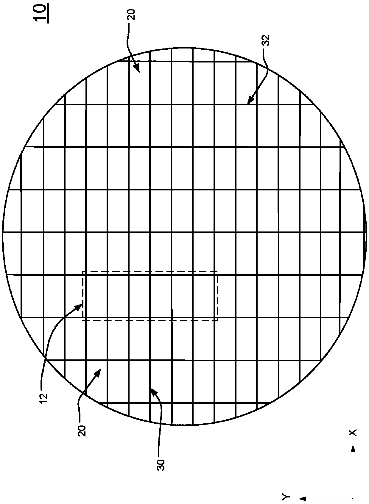
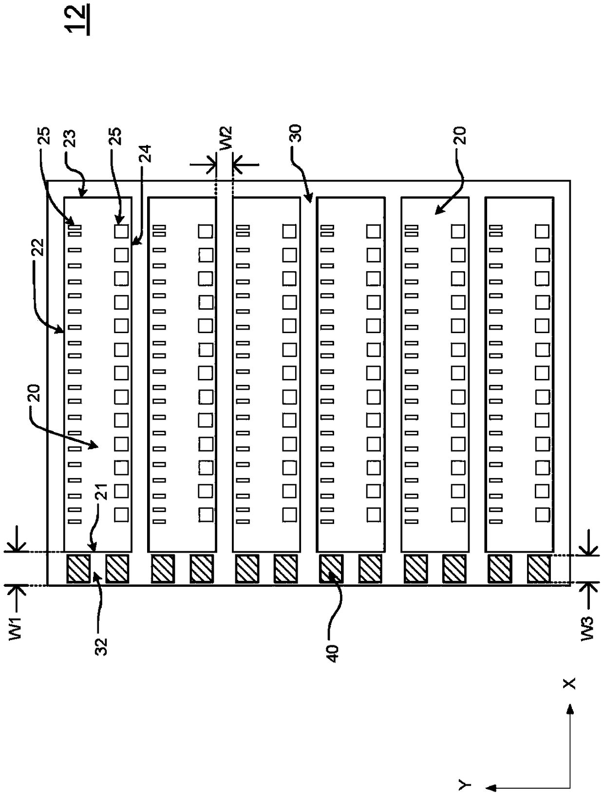
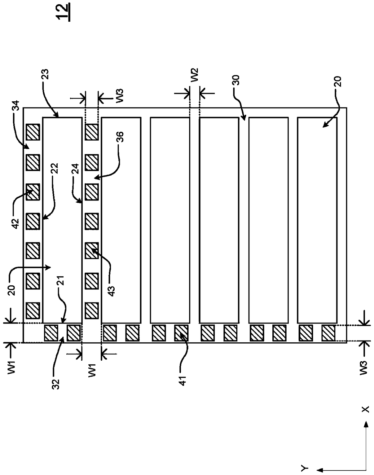
[0044] see figure 1 , which is a schematic diagram of an embodiment of the wafer structure of the present invention...


PUM


Abstract

The invention provides a wafer structure, comprising a plurality of particles, a plurality of cutting channels, and a plurality of process patterns. The cutting channels are disposed at first edge andsecond edge of adjacent particles. The process patterns are collectively disposed in the cutting channel of the adjacent first edge, or in the particles, or collectively disposed in the cutting channel of the adjacent first edge and a part of the cutting channel of the adjacent second edge. Accordingly, when the width of the cutting channel having no process patterns is reduced, the quantity of particles, generated by each wafer can be increased.

Description

technical field [0001] The present invention relates to a wafer structure, in particular to a wafer structure in which process patterns are concentrated on some cutting lines or concentrated on crystal grains. Background technique [0002] In the development of electronic products and the evolution of technology, integrated circuit (Integrated Circuit, IC) design companies and wafer foundries both want to increase the number of grains that can be produced by a wafer, and one of the commonly used methods is to reduce The width of the scriber line, but the grain often needs to rely on the process pattern on the scribe line to check its correctness during the manufacturing process. However, the capability of the manufacturing equipment has its limit, and the process pattern cannot be reduced beyond the capability of the manufacturing equipment. As a result, the narrowing of the cutting lane is limited. Based on the above-mentioned problems, the State Intellectual Property Offi...

Claims


Application Information

Patent Timeline
IPC IPC(8): H01L29/06H01L21/304
CPCH01L29/06H01L21/304H01L21/76H01L21/02002H01L21/3213
Inventor 林春生吴谷泽简志颖周明宗
Owner SITRONIX TECH CORP
Learn More