
A multilayer bandpass filter

A technology of filters and multi-layer tapes, applied in waveguide devices, electrical components, circuits, etc., can solve the problems that the resonator coupling cannot be adjusted, cannot meet the required performance of the device, and the device volume is not easy to install, etc., to achieve reduction The installation occupies an area, meets the performance, and the effect of small size

Inactive Publication Date: 2019-01-04
苏州市矩光达通讯技术有限公司
View PDF0 Cites 0 Cited by
  • Summary
  • Abstract
  • Description
  • Claims
  • Application Information

AI Technical Summary

Problems solved by technology

[0005] The purpose of the present invention is to provide a multi-layer bandpass filter to solve the problem that the resonators of the existing filter proposed in the above background technology are concentratedly installed on the same dielectric layer, resulting in a large occupied area, resulting in excessive volume of the device. Large and difficult to install, and the amount of coupling between resonators cannot be adjusted, resulting in problems and deficiencies such as the inability to meet the performance required by the device itself

Method used

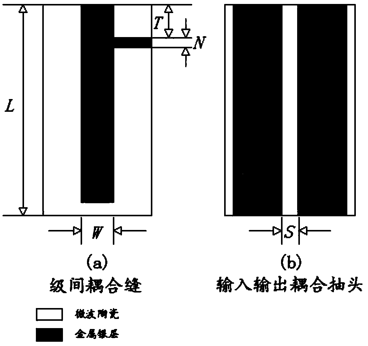
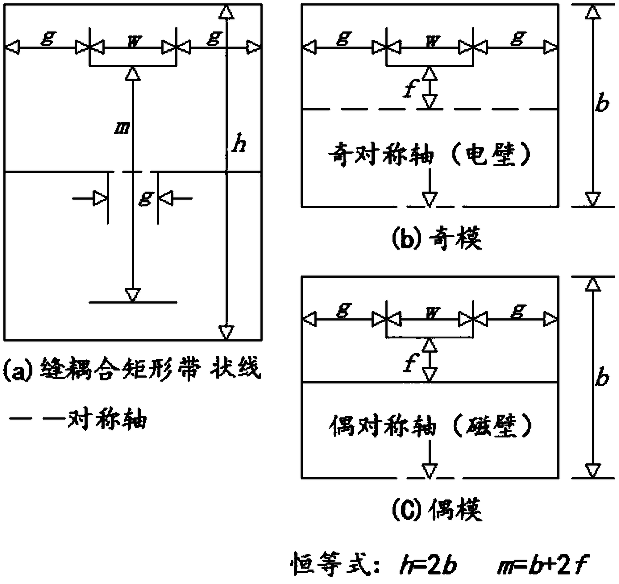

Image

  • A multilayer bandpass filter
  • A multilayer bandpass filter
  • A multilayer bandpass filter

Examples


Embodiment approach

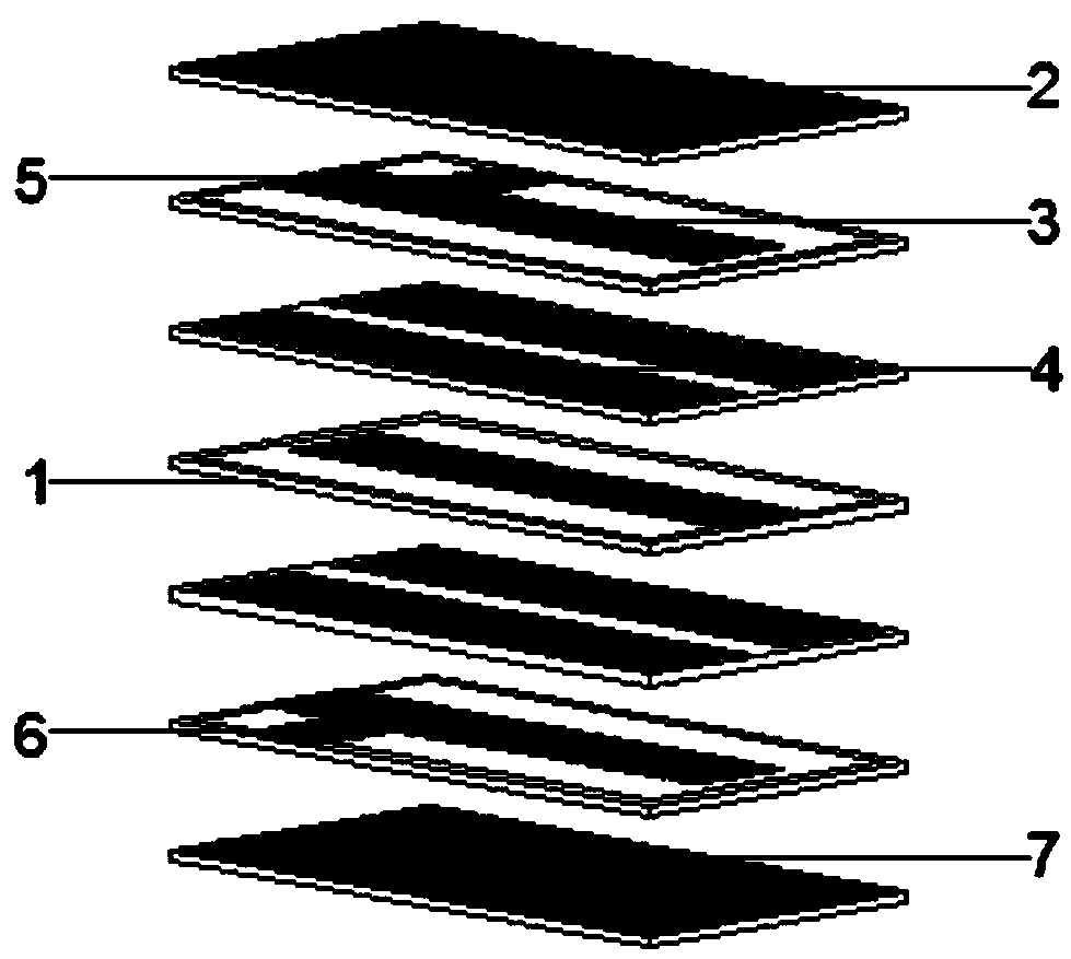
[0027] A multilayer bandpass filter, comprising: a dielectric layer 1, a floating ground 2, a stripline resonator 3, a coupling slot 4, an input port 5, an output port 6, and a system ground 7; the dielectric layer 1 is sequentially stacked with seven layer; the floating ground 2 is located on the dielectric layer 1 of the top layer, and the floating ground 2 is composed of capacitor electrode ground; the stripline resonator 3 is respectively located on the dielectric layer 1 of the second layer and the sixth layer from top to bottom, and the band The linear resonator 3 is composed of an inductor and a capacitor inductance; the coupling slot 4 is located on the dielectric layer 1 of the third layer and the fifth layer from top to bottom, and the coupling slot 4 is composed of an odd mode and an even mode; the input port 5 It is located on the dielectric layer 1 of the second layer from top to bottom, and the input port 5 is composed of an input terminal LC resonator; the output...


PUM


Abstract

The invention relates to a multilayer bandpass filter, comprising a dielectric layer, a stripline resonator and a coupling slot. 7 layer are arranged on that dielectric lay in order of superposition;The stripline resonator is respectively located on the dielectric layer of the second layer and the sixth layer from the top to the bottom, and the stripline resonator is composed of an inductor and acapacitor inductor. The coupling slot is respectively located on the dielectric layer of the third layer and the fifth layer from the top to the bottom, and the coupling slot is composed of an odd mode and an even mode. By improving the dielectric layer and the coupling slot, the invention has the advantages of small volume, convenient installation, adjustable coupling amount, meeting the performance required by the device itself, and the like, thereby effectively solving the problems and shortcomings proposed in the background of the invention.

Description

technical field [0001] The present invention relates to the technical field of electronic components, and more specifically, relates to a multilayer bandpass filter. Background technique [0002] The filter can effectively filter the frequency point of a specific frequency in the power line or the frequency other than the frequency point, obtain a power signal of a specific frequency, or eliminate a power signal of a specific frequency, and is widely used in electronic equipment. [0003] However, the existing filters occupy a large area because the resonators are concentratedly installed on the same dielectric layer, which makes the device difficult to install due to its large size, and the coupling between the resonators cannot be adjusted, resulting in the inability to meet the needs of the device itself. performance etc. [0004] In view of this, the existing problems are researched and improved, and a multi-layer bandpass filter is provided, aiming at solving the probl...

Claims


Application Information

Patent Timeline
Patent Type & Authority Applications(China)
IPC IPC(8): H01P1/203
CPCH01P1/203
Inventor 杨平易认
Owner 苏州市矩光达通讯技术有限公司
Learn More