
Distribution cabinet

A technology for power distribution cabinets and cabinets, which is applied to the substation/power distribution device shell, electrical components, substation/switch layout details, etc., which can solve the problem that the heat dissipation effect of the power distribution cabinet cannot achieve the desired effect, and the power distribution cabinet cannot dissipate heat in time , Power distribution box and other problems, to achieve good sound insulation effect, improve insulation effect, improve the effect of heat dissipation

Inactive Publication Date: 2019-01-04
YANCHENG POWER SUPPLY CO STATE GRID JIANGSU ELECTRIC POWER CO +4
View PDF5 Cites 3 Cited by
  • Summary
  • Abstract
  • Description
  • Claims
  • Application Information

AI Technical Summary

Problems solved by technology

[0004] In addition, due to the installation of a large number of connectors and various electronic components in the power distribution cabinet, and the existence of a large number of wires, the total resistance of the power distribution cabinet is very high, because it will emit A large amount of heat makes the temperature of the power distribution cabinet suddenly increase, and the power distribution cabinet is often compact in structure, small in space and closed, so the heat dissipation effect of the power distribution cabinet generally cannot achieve the desired effect, especially in During the peak period of use, the failure of the power distribution cabinet to dissipate heat in time will easily lead to damage to the components in the power distribution cabinet, or even explosion or fire accidents. At the same time, the components have high requirements on the environment in the power distribution cabinet, because the electrical appliances inside Components are very afraid of dust and debris, etc. These debris and dust can cause some resistance to increase the temperature of the power distribution cabinet, so it will cause high temperature in some places, and then danger will occur; the power distribution box of various electronic components in the power distribution cabinet is compared Large, causing relatively loud noise

Method used


Image

  • Distribution cabinet
  • Distribution cabinet
  • Distribution cabinet

Examples


Embodiment Construction

[0021] The present invention will be further described in detail below in conjunction with the embodiments, so that those skilled in the art can implement it with reference to the description.

[0022] This case proposes a power distribution cabinet according to an embodiment, which includes a cabinet body and a cabinet door that can be opened and closed on the cabinet body. A temperature sensor, a humidity sensor and a dehumidifier are arranged on the inner surface, a display is arranged on the outer surface of the cabinet door, and the output terminals of the temperature sensor and the humidity sensor are electrically connected to the display; a fan and several The desiccant is packed in bags, and a first switch for controlling the start and stop of the fan and a second switch for controlling the start and stop of the dehumidifier are arranged on the outer surface of the cabinet door.

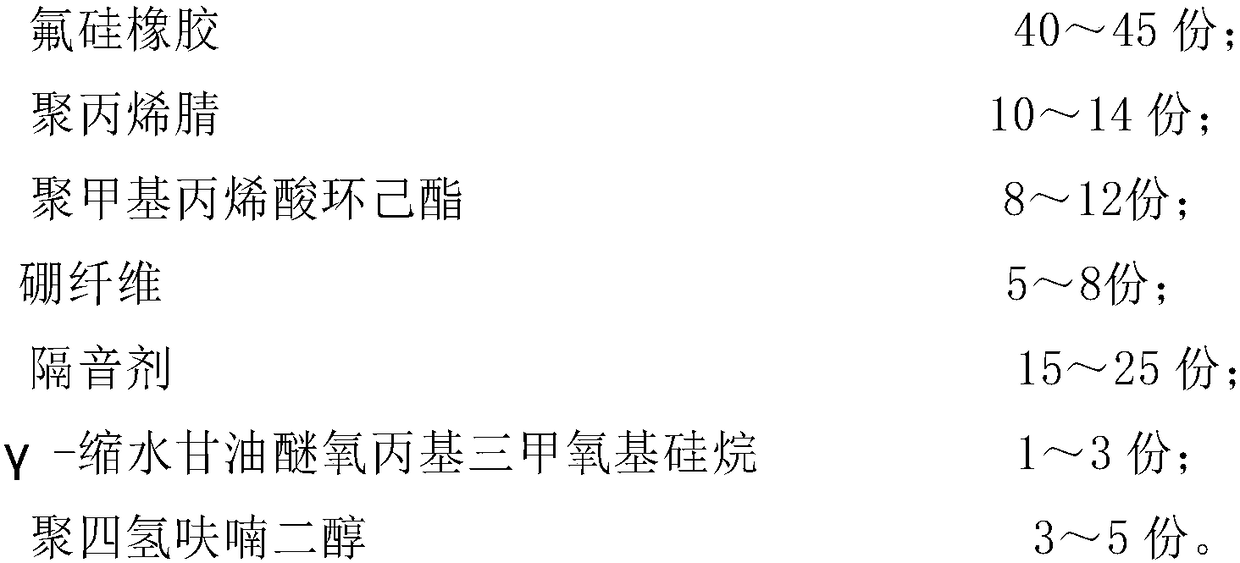
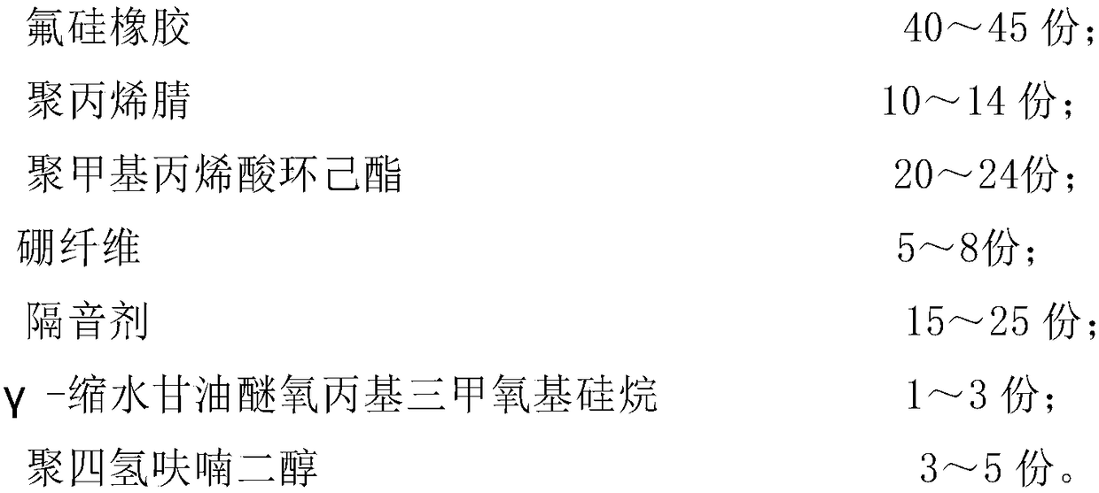
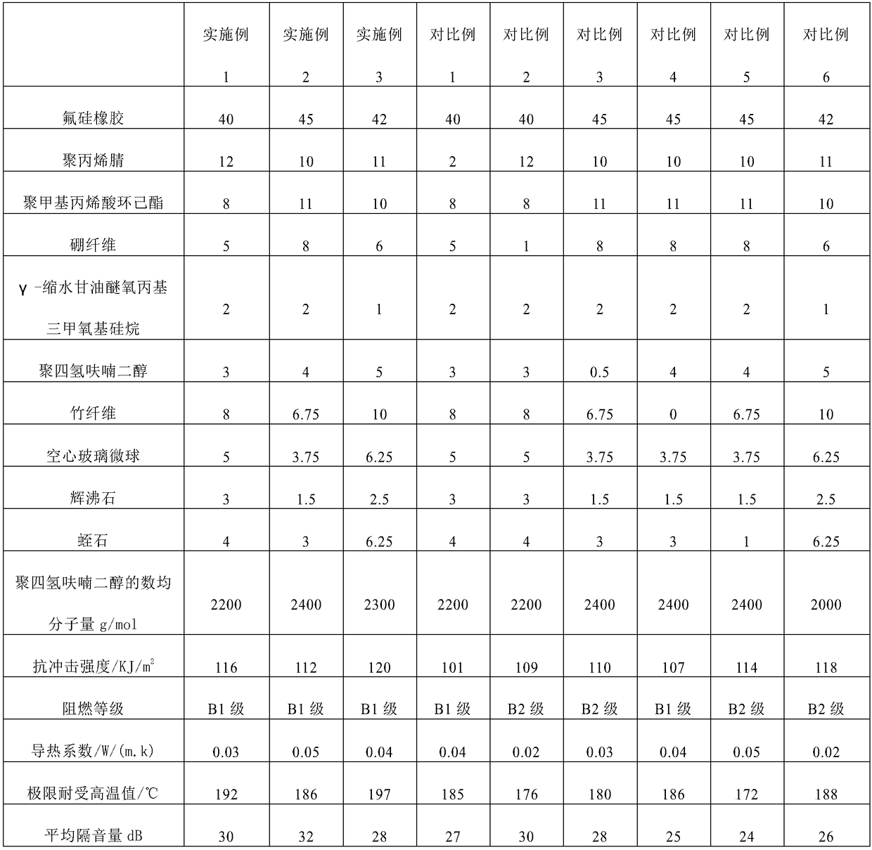
[0023] Wherein, the cabinet body includes a steel plate layer and a sound insulation laye...


PUM


Abstract

The case relates to a distribution cabinet, which comprises a cabinet body and a cabinet door which can be opened and closed and arranged on the cabinet body, The cabinet body comprises a ventilationtop cover, a bottom plate, a left side plate, a right side plate and a back plate; a temperature sensor, a humidity sensor and a dehumidifier are arranged on the inner surface of the back plate; a display is arranged on the outer surface of the cabinet door; the output ends of the temperature sensor and the humidity sensor are electrically connected with the display; The inner surface of the bottom plate is provided with a fan and a plurality of bags of desiccant. The outer surface of the cabinet door is provided with a first switch for controlling the start and stop of the fan and a second switch for controlling the start and stop of the dehumidifier. The cabinet body comprises a steel plate layer and a sound insulation layer fixed in the steel plate layer. The distribution cabinet of theinvention has high heat dissipation performance and good sound insulation effect, effectively protects internal components, improves safety performance and prolongs service life.

Description

technical field [0001] The invention relates to the technical field of electric equipment, in particular to a power distribution cabinet. Background technique [0002] The power distribution cabinet is an important part of the power distribution and transmission industry. It is a high-voltage or low-voltage distribution cabinet that assembles switchgear, measuring instruments, protective appliances and auxiliary equipment in a closed or semi-closed metal cabinet or on a screen according to the requirements of electrical wiring. Electrical device, during normal operation, the circuit can be connected or disconnected by manual or automatic switch, and the circuit can be cut off or alarmed by the protection device when it is faulty or abnormal. Adjust the parameters, prompt or send out signals for deviations from normal working conditions, and are often used in various power generation, distribution, and substations. [0003] The use environment of some power distribution cabi...

Claims


Application Information

Patent Timeline
Patent Type & Authority Applications(China)
IPC IPC(8): H02B1/56H02B1/28H02B1/32H02B1/54C08L83/08C08L33/20C08L33/10C08L97/02C08K13/04C08K7/28C08K3/34C08K7/06
CPCC08L83/08C08L2205/035C08L2205/16H02B1/28H02B1/32H02B1/54H02B1/565C08L33/20C08L33/10C08L97/02C08K13/04C08K7/28C08K3/34C08K3/346C08K7/06
Inventor 周昕孟亚宏李海青于峰李大伟
Owner YANCHENG POWER SUPPLY CO STATE GRID JIANGSU ELECTRIC POWER CO
Learn More