
Optical thin film, mould and cover plate of electronic equipment

A technology of optical film and electronic equipment, applied in the direction of optics, electrical equipment shell/cabinet/drawer, optical components, etc., can solve the problems of cumbersome process, single shell or cover plate, increase film thickness, etc., to reduce cost and thickness and the effect of the manufacturing process

Inactive Publication Date: 2019-01-04
SHINE OPTOELECTRONICS KUNSHAN CO LTD
View PDF4 Cites 0 Cited by
  • Summary
  • Abstract
  • Description
  • Claims
  • Application Information

AI Technical Summary

Problems solved by technology

[0004] At present, the decorative film used in 3C products or household appliances generally has a planar structure and the visual effect is also a planar effect, so that the shell or cover of the 3C product or household appliances is relatively simple; on the other hand, the use of imaging films on 3C products or household appliances, Such a two-layer film structure increases the thickness of the film, and the process is cumbersome and increases the cost; therefore, it is necessary to provide a new technical solution to solve this technical problem

Method used


Image

  • Optical thin film, mould and cover plate of electronic equipment
  • Optical thin film, mould and cover plate of electronic equipment
  • Optical thin film, mould and cover plate of electronic equipment

Examples


Embodiment Construction

[0041] In order to facilitate the understanding of the present invention, the present invention will be described more fully below with reference to the associated drawings. Preferred embodiments of the invention are shown in the accompanying drawings. However, the present invention can be implemented in many different forms and is not limited to the embodiments described below. On the contrary, the purpose of providing these embodiments is to make the disclosure of the present invention more thorough and comprehensive.

[0042] It should be noted that when an element is referred to as being “disposed on” another element, it may be directly on the other element or there may also be an intervening element. When an element is referred to as being "connected to" another element, it can be directly connected to the other element or intervening elements may also be present. The terms "vertical," "horizontal," "left," "right," and similar expressions are used herein for purposes o...


PUM

PropertyMeasurementUnit
depthaaaaaaaaaa

Abstract

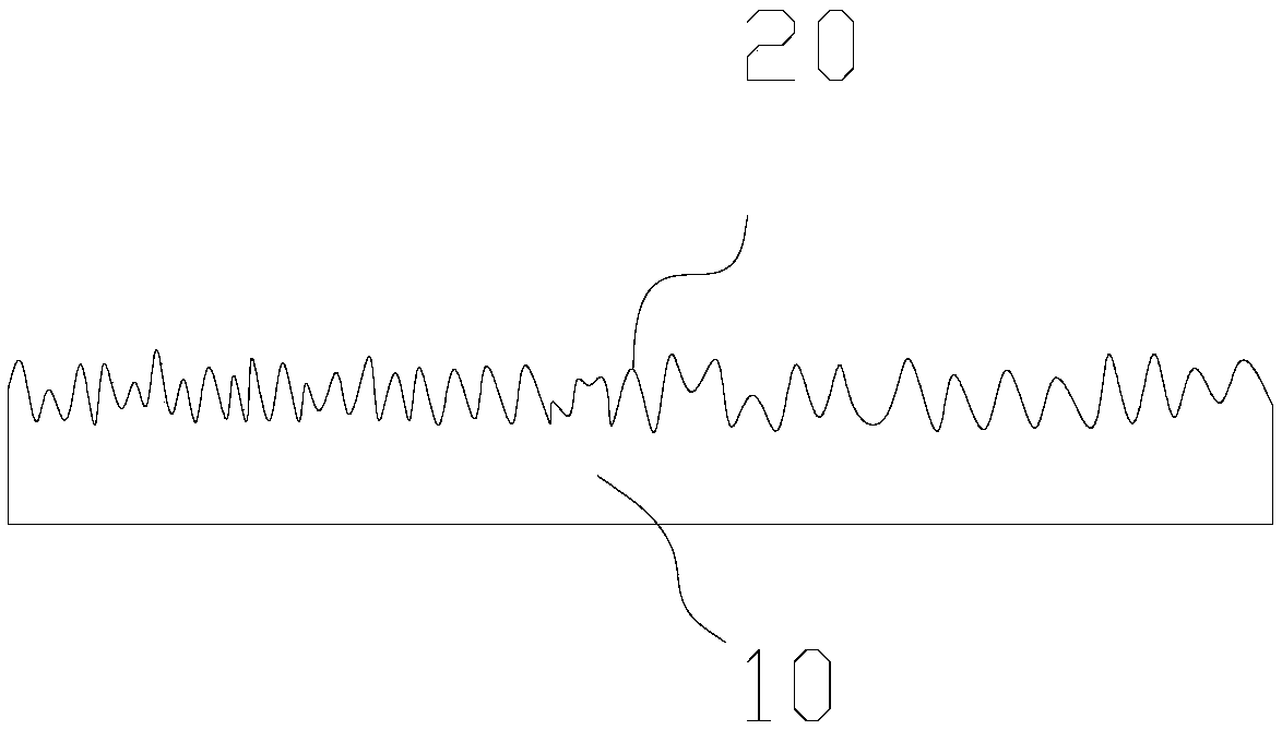
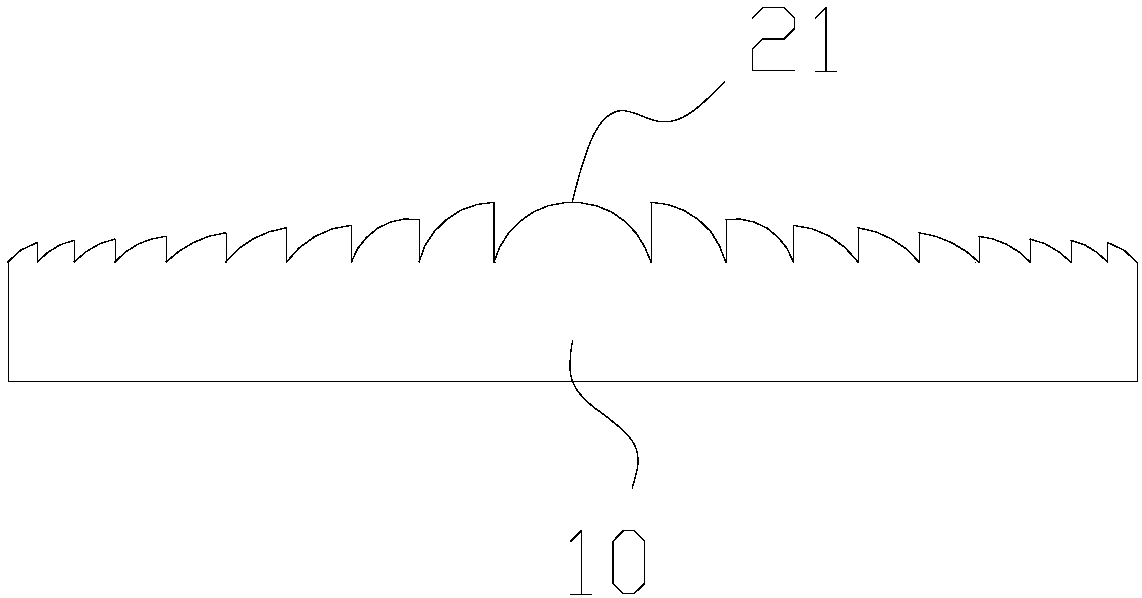
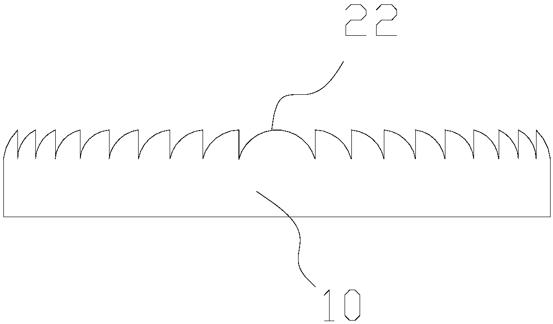
The invention discloses an optical thin film, a mould and a cover plate of an electronic equipment, wherein the optical thin film is characterized in that: A graphics structure layer located on a surface of the carrier, the graphics structure layer comprising a continuously arranged micro-nano structure, the micro-nano structure being a convex structure and / or a concave structure; Wherein the optical film visually has a stereoscopic feeling of a depth or height of not less than 1 mm. The optical film provided by the invention is provided with a graphics structure layer, and the graphics structure layer is arranged in a continuous micro-nano structure, so that stereoscopic effect can be realized by only using the one-layer structure, and visual difference of at least 1mm depth or height exists, so that the thickness of the film and the manufacturing process are reduced, and the cost is reduced well.

Description

technical field [0001] The invention relates to the technical field of optical films, in particular to an optical film, a mold and an electronic equipment cover plate. Background technique [0002] With the development of science and technology, decorative films are widely used on the surface of electronic products such as mobile phones, computers, household appliances such as refrigerators, air conditioners, washing machines, and automobiles. [0003] Existing decorative films are used as surface materials for mobile devices such as mobile phones and notebook computers, and as surface materials for molding household appliances such as refrigerators, washing machines, and air conditioners. used. [0004] At present, the decorative film used in 3C products or household appliances generally has a planar structure and the visual effect is also a planar effect, so that the shell or cover of the 3C product or household appliances is relatively simple; on the other hand, the use ...

Claims


Application Information

Patent Timeline
Patent Type & Authority Applications(China)
IPC IPC(8): H05K5/03H05K5/02G02B27/22
CPCG02B30/27H05K5/0243H05K5/03B29D11/00269B29D11/00788G02B30/40
Inventor 高育龙洪莘申溯亢红伟
Owner SHINE OPTOELECTRONICS KUNSHAN CO LTD
Learn More